Its all about time!
Why did I do this?
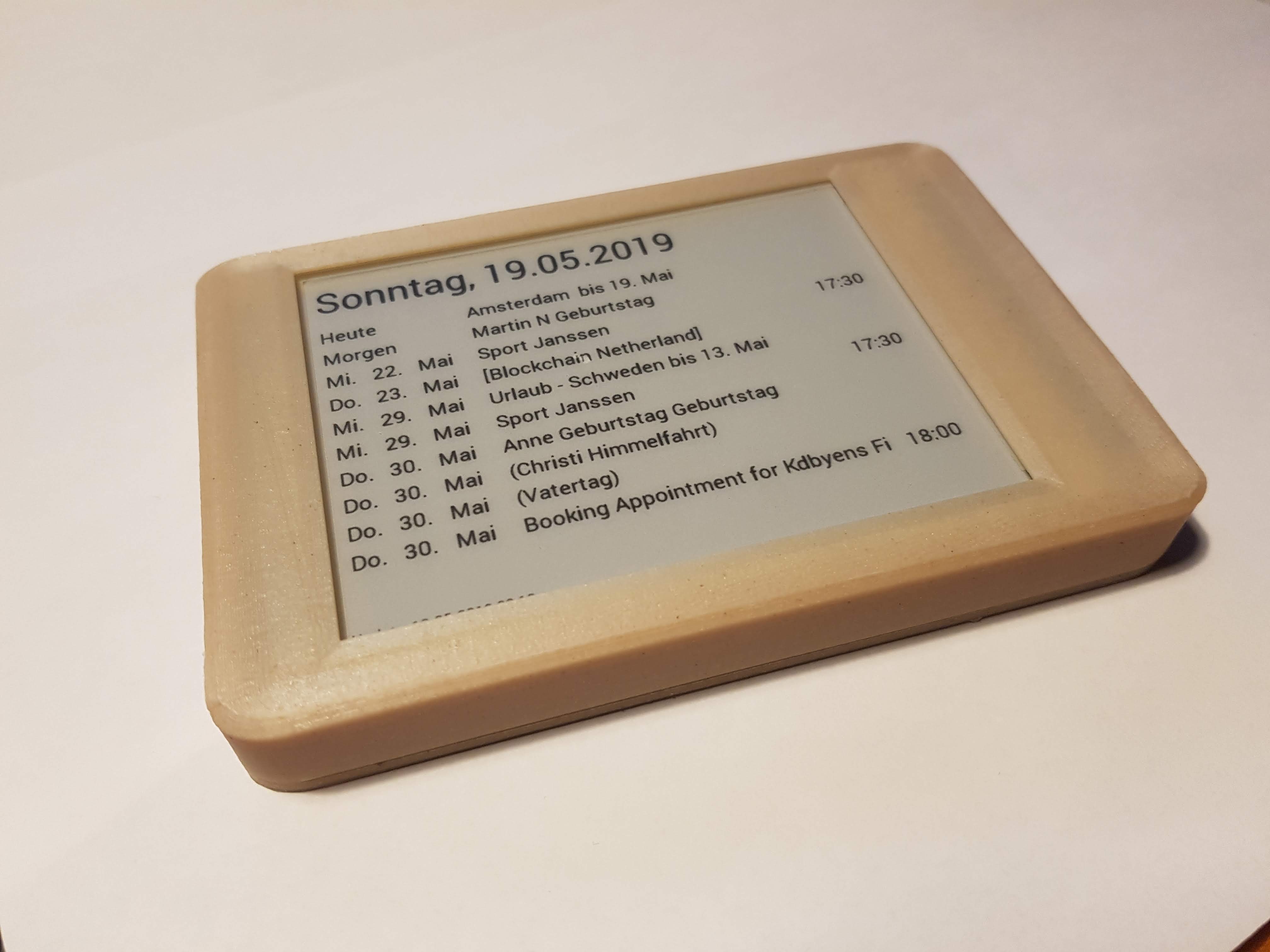
Since many years I am using Google Calendar, believe me I was an early adaptor. But what does it help, in real live…when nobody is looking at it. The master calender is in the kitchen .. and its on paper. So, this can be changed. Now we have one central place, you see what is going on the next weeks.
What did I do?
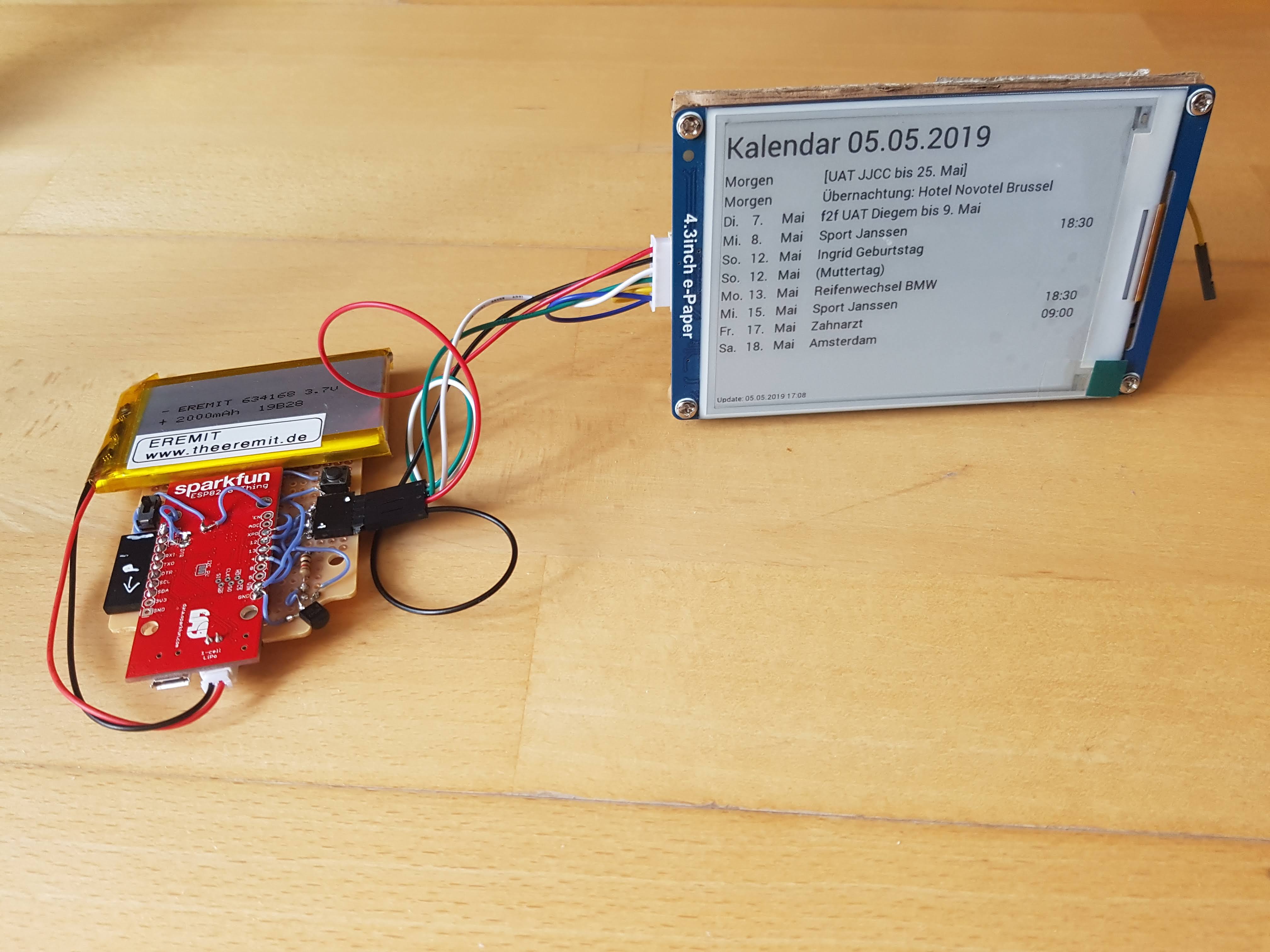
Over night the “Calendar” downloads the upcoming events from the Google Calendar and updates the display with this information. Because this is an e-Ink Display the events are displayed all day without any power – consumption. The access to Google is save and secure via HTTPS and OAUTH.
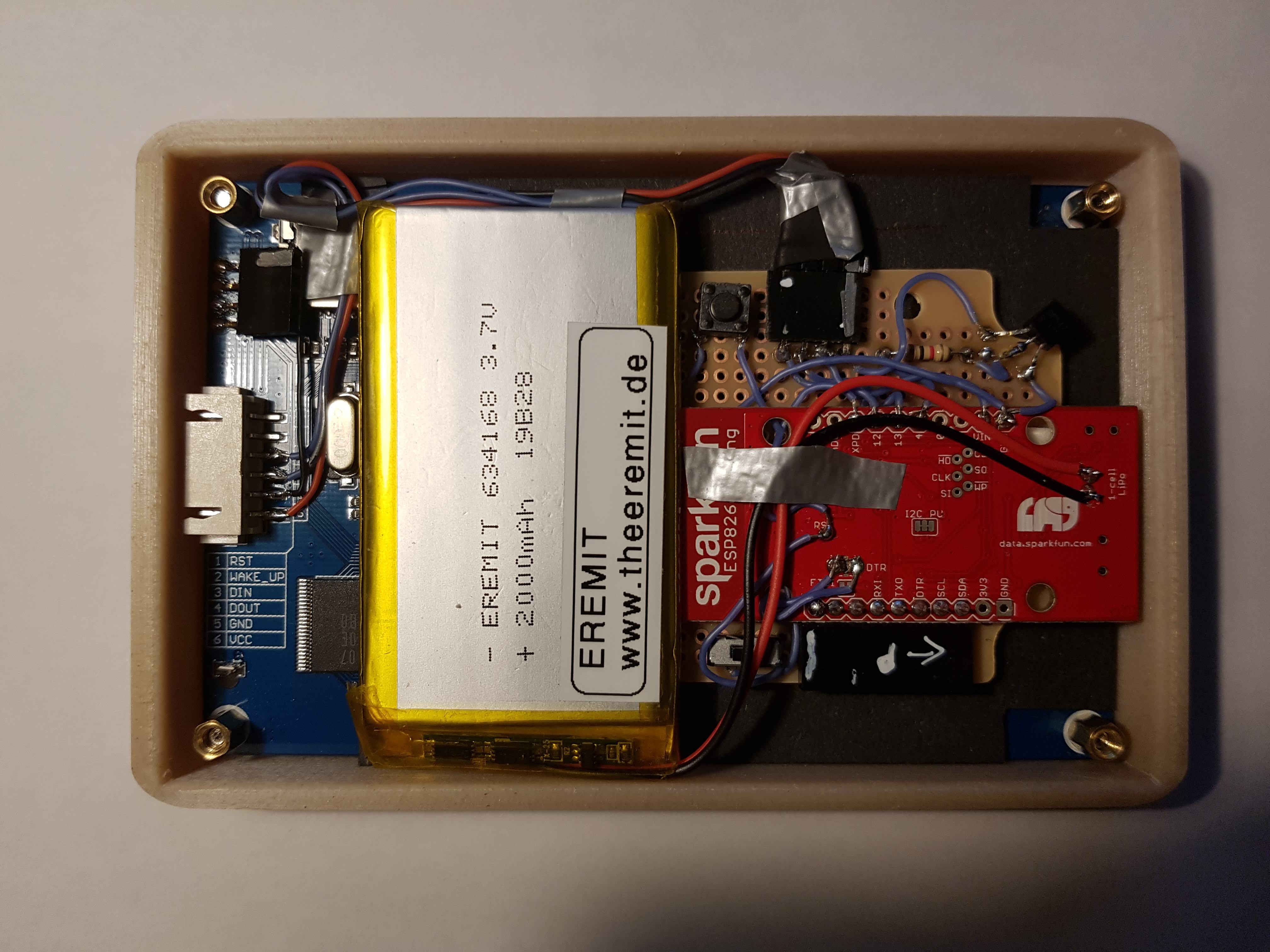
- using the eInk Display to save power (only needs power once a day)
- runs over 160 days without recharging
- supports multiple Goolge calendars
- flexible configuration via USB card (Wifi, Calender Text, Calendars used)
- support Google OAUTH 2 with DeviceCode
- secure using HTTPS certificate validation
- case designed using 3d printing
How does it work?
If you want to know more…read here:
>>> How does it REALLY work in detail? <<<
Technical Docs
Latest News
[display-posts category=”calendar” include_content=”true” image_size=”thumbnail” include_date=”true” date_format=”(d.m.Y)”]