
How does it work?
The Calendar has two components, the ESP8266 handling the WIFI Communication and the Waveshare eInk Display to show the calender information.
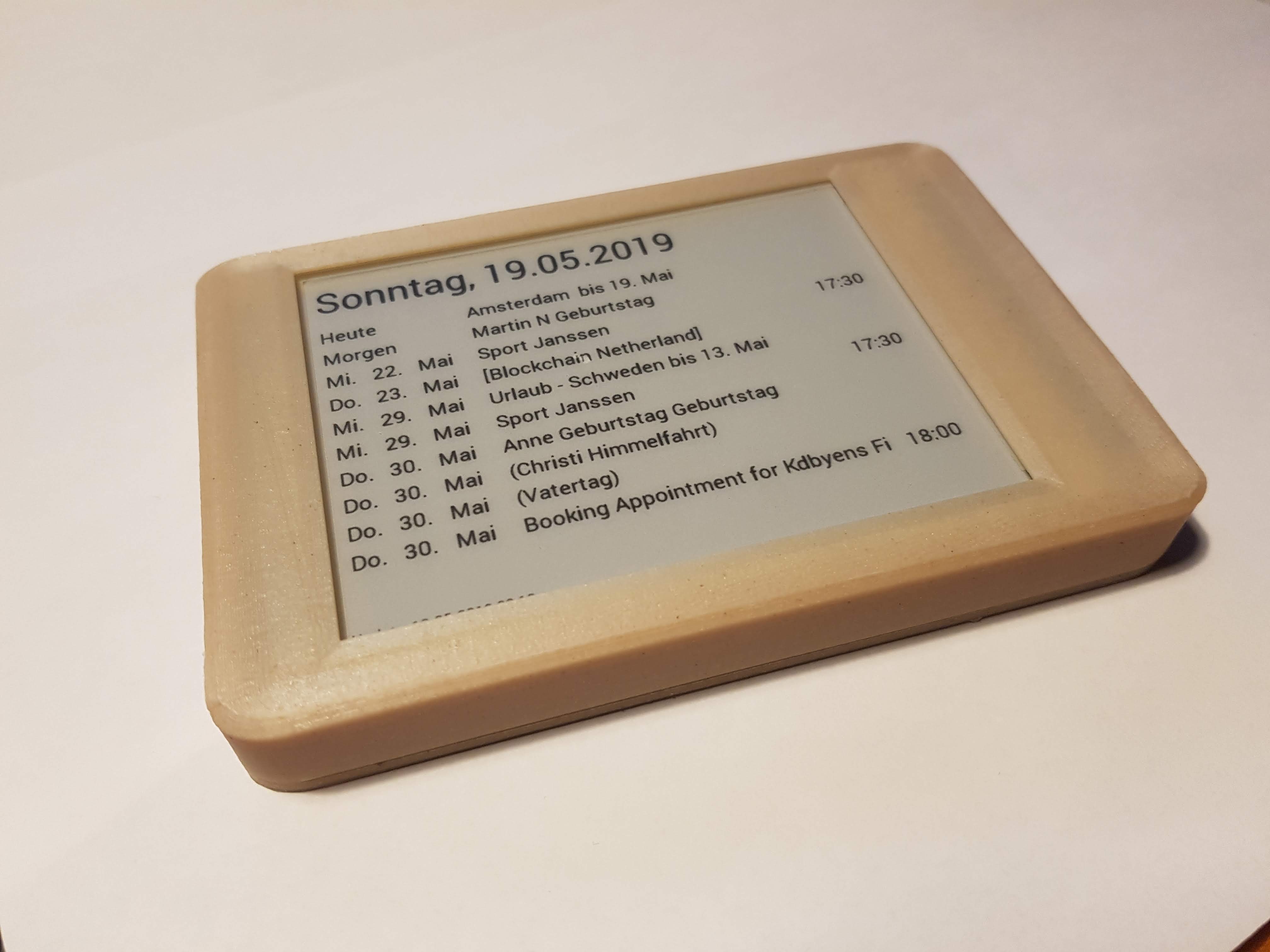
Overview
The calendar is displayed on the UART Waveshare eInk display (800×600 Black&White) powered by an STM32-F103 ZE with 512kB Flash, 64kb RAM and 1MB SRAM. Thanks to David (see link) we could remove the existing firmware and are able to program the STM32 via JTAG. This enabled me to use the memory (1MB RAM) to prepare the picture, the SD Card to configure WIFI and to use the STM32 computing “power” to parse the JSON Calendar information from Google.
The ESP8266 (ESP8266 Thing) is used to communicate with Goolge and return the JSON file with the calendar information
ESP8266 – Managing WakeUp, HTTPS, Google OAUTH
ESP8266 (ESP8266 Thing) can sleep only for 2hours. Its using RTC memory on the Thing board to count the numbers of wake-ups. Its programmed to really wake-up at 2pm (GMT) and will power the eInk Display. Via Serial Interface (pin 12/12 on ESP and RX/TX on eInk) the display reads the SD Card WIFI information and sents them to the ESP.
Using this WIFI information, the ESP will connect to the Google Calendar API using HTTPS.
LEARNING
HTTPS is only as save the the certificate validation, IOT devices may skip this and allow Man-in-the-Middle-Attacks – that could reveal your Google credentials. An alternative solution is to use the FINGERPRINT (Hash) of the pages certificate, but this may stop working as soon as the certificate expires or any change was done at the certificate. In my solution I downloaded Google Root Certificates and stored it in the ESP ROM. When connecting to Google Calendar API the complete certificate chain is validated from the Root Certificate to the Page Certificate. Feels much more secure 🙂
Once connected the ESP will follow the OATH authentication process (Google OAUTH). Initially or when the authentication with Google fails, the ESP restart the authentication and displays a DEVICE-CODE on the eInk display that needs to be entered into the Google Web-Page to pair the device.The Refresh-Token obtained from this process is stored in the RTC memory – so it can be re-used for the next wake-up and no paring is needed.
Once the authentication is completed the ESP will receive the Google-Calender information from the SD-Card of the eInk – Display and request the JSON calendar information via the authenticated connection. This is directly sent to the STM32 eInk Display processor.
eInk Display – STM32 – Display text on the eInk Display
As the original firmware was removed, I implemented a graphical library that is able to write text (different font types and sizes) using Fontem. Fontem takes a TTF font and generates C-Header files with keep the font information. It supports KERNING, so the space between the characters is looking nice.
eInk Display – STM32 – Memory Management
The Graphical Libary is using an 800*600*2 (each pixel is represented by 2 bits) memory buffer (not enough memory for the STM32 internal memory, so it needs to be stored in the external 1MB SRAM of the display.
The external RAM is set-up to be accesseable via address 0x68000000. By adjusting the link.ld file I can define which memory is used for the calloc/malloc. By using below the HEAP address is set to XRAM (external RAM) and calloc/malloc is taking this memory. This is not very performant, but as the display runs over night, this doesn’t matter.
MEMORY
{
FLASH (rx) : ORIGIN = 0x08000000, LENGTH = 512K
SRAM (rwx) : ORIGIN = 0x20000000, LENGTH = 64K
<strong>XRAM (rwx) : ORIGIN = 0x68000000, LENGTH = 1M</strong>
}

__rom_start__ = ORIGIN(FLASH);
__rom_size__ = LENGTH(FLASH);
__ram_start__ = ORIGIN(SRAM);
__ram_size__ = LENGTH(SRAM);
__ram_end__ = __ram_start__ + __ram_size__;
__stack_end__ = __ram_end__; /* Top of RAM */
__stack_size__ = 16K;
__stack_start__ = __stack_end__ - __stack_size__;
__heap_start__ = ORIGIN(XRAM);
__heap_end__ = ORIGIN(XRAM) + LENGTH(XRAM);
end = __heap_start__;
Little Tip: To make the debugger aware of this memory mapping change, you can enter in the gdb:
mem 0x68000000 0x680FFFFF rw
eInk Display – STM32 – Driving the display
The Waveshare – Board is using the E-ink display GDE043A2 (Good-Display.com). The communication between the STM32 and the GDE043A2 is using SPI. Driving the display via SPI is complex and requires a lot of knowledge. Thx to David (see link section) he reversed the original firmware and the basic functions are provided on GitHub. I am using his functions to actually write the graphic buffer to the display. The logic is covered in the file stm32_application/gde043a2.c.
Build Environment for the Waveshare STM32 e-Ink Display
Normally I am using Platformio to build the firmware for any Arduiono or ESP8266 device (check the platformio.ini for the ESP8266).
For the STM32 this is not working, we need to set-up a GNU Arm Embedded Toolchain ( PPA for -arm-embedded on UBUNTU) for cross compiling and then upload the firmware to the board. The communication goes via the JTAG interface controlled via the ST-LINK adapter (connected via USB to the developer PC and via JTAG to the board). For this we need to install the ST-Utils and run “st-utils” in background, that pushes the cross-compiled code from the development PC to the board.
Two files are important to control the build flow:
- CMakeLists.txt: Controls the cross-compiling logic (generate the *ELF file for upload executes upload)
- STM32F10x.cmake: Controlls the actual compiler options for the STM32 and defines the cross compiler
COOL – Using Remote Debugging the STM32 can be debugged right out-of the CLION – IDE using all features available: