

Latest News
 Thank you for your order with Banggood – or how to build a Smart Home Switch for $4.00 (26.01.2020)
It all started with an article in my favourite computer magazine Heise – WLAN Plug with Tasmota. So I could control some 220V devices, like a floor lamp with my OpenHAB Super-Cheap – Smart Home Solution Smart Home.
Some 220V devices don’t need a plug, I want to control them with a tiny switch and not a big plug on the wall, here I found this- 4€ each from China…will this work?

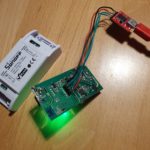
After one month of waiting, 3 arrived. Looked actually quite good!
Its actually amazing, what you get for 4€, and ESP8266 micro computer with WiFi and all the hardware to control 220V / 10 A = 2200W)
But: Its firmware is from China, you need to register an account somewhere and the little switch will connect to it and send your data somewhere – I cannot control.
Wo we need to exchange the firmware on the switch, the brand “Sonoff” is well known for an “easy to way” to do this
The firmware solution of my choice is Tasmota, an OpenSource SW that connects the device only into the internal WiFi network and provide a user-interface to configure the device. So we need to do 2 things to get it running:
- Flash new Firmware flashed on the switch
- Integrate the switch into OpenHAB (smart home open source SW)
Preparation
Pretty easy thing (all here: Details), you need:
- Image “tasmota.bin” from Tasmota: https://github.com/arendst/Tasmota/releases
- Flashsoftware to reprogram the device with the image from 1): tasmotizer
- A wire to to connect your PC via an FTDI (serial2USB converter) with the switch, the FTDI and the switch have signs on it, so has the switch:
Edit FTDI Sonoff Smart Swtich 3V 3V GND GND TXT REC/RXI REC/RXI TXT It takes 5min of soldering, when ready it should look similar to below:

Flashing
The switch needs to be connected with the PC via our nice cable, it just works by putting it in and a bit of adjusting.
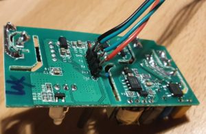
To get the switch in the “programming mode” the reset-button on the switch must be pressed *before* connecting the switch via USB cable to the PC. Once connected, you can release the reset-button (its the long black stick).

Then start flashing with tasmotizer by selecting the firmware and the USB interface:

After re-power the switch, it opens an access-point and you can be configured via connecting to its WiFi (some AP with “tasmota” in the name) , so it will later connect to your own WiFi. But much more elegant, you can use tasmotizer via the button “send config” to update the WiFi directly, you will need to enter the credentials (SSID and PWD from your home network).
All your credentials and data remain will remain in your network now. On the router I also disabled the internect-connection for the IP address of the switch in my home network – just to be save 🙂
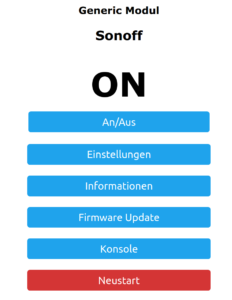
Configure the Switch – Tasmota is great
When all works, the switch will connect to your home WiFi, you can find its IP address in your Router and you can open its main config page via a web-browser. You will see the new firmware from “Tasmota” active, that gives you full control over the device.
Its an amazing software, full Opensource, not cloud connection or internet needed. It stays in you home 🙂
The basic tasmota configuration is already correct, nothing to do, maybe in the settings section, you may enter a backup WiFi address – if you want.
Connecting to OpenHAB
The Switch Side
The concept is, that the switch will use the MQTT protocol to communicate with OpenHab, once configured the switch will listen for a message via this protocol and do its job – ON/OFF.

To configure MQTT you need configure your OpenHab server IP and the credentials of the MQTT network, that you have configured in OpenHab. The trick is the “topic”, that is the “address” that the switch will listen towards – any message with this topic will be processed by the switch. For my network I gave each switch its own topic, like “sonoff1”, “sonoff2” – so I can control them separately. OpenHab has a binding that keeps the link to this protocol and its easy to configure.
The OpenHab Side
After installing the MQTT Binding in OpenHab, I did the following configuration, important to have the topic “sonoff1” correctly everywhere:
Bridge mqtt:broker:OH2mqtt "MQTT Broker" @ "MQTT" [
    host="192.168.1.106",
    port=1883,
    username="OpenHAB",
    password="xyz"

] {
    Thing topic sonoff1 "Sonoff1" @ "MQTT" {
     Channels:
     Type switch : ch1  "Light1" [ stateTopic="sonoff:stat/sonoff1/POWER", commandTopic="cmnd/sonoff1/POWER" ]
    }
}
To enable and disable the switch, its straight forward:
Switch Sonoff1 "Light1"  	 	 	 	 	 	 	 	<light> ["Switchable"] { channel="mqtt:topic:OH2mqtt:sonoff1:ch1" }

 sendCommand(Sonoff1,ON)</light>
Enjoy 🙂

 About Amazon Dash-Buttons, and what you can learn from it about IoT and Amazon! (19.01.2020)
I am using Amazon-Dash buttons in my home automation project, got them from eBay for some euro. So I can switch-off all lights and heating from my bed, dim the lights in the living-room when watching TVs. And all for nearly no money. The buttons a made for 1000 clicks, so I thought I would be save.
But I didnt realize the “power of Amazon” and under-estimated the SW and HW that is build into this little button.

My plan – how to use the “Dash-Button” in Home Automation!
Amazon did everything to make the button not useable – except for ordering from Amazon 🙂
But smart people found a solution: You set-up the button once with the Amazon App (to let him connect to your WiFi network by providing SSID and PWD) .
When the button is pressed, it wakes up and needs to re-connect to the configured WiFi , this connection event can be monitored with a simple script to install on RPI HomeServer with Openhabian: https://github.com/Nekmo/amazon-dash
sudo apt-get remove python3-pip; sudo apt-get install python3-pip
sudo pip3 install amazon-dash
<code class="yml">sudo systemctl start amazon-dash
Finally you need to configure the buttons (name, mac-address) to be controlled in a config-file That’s it – you can access the button from OpenHABian like any Hue device.
Ohnn…not really…..its important you make it impossible for the button to “CALL HOME” to Amazon (e.g. with a FritzBox you disable internet for fixed IP address of the button).
The big disappointment!
One day, one button stopped working.It seems that the battery is empty. Ok, no problem – took me a while to open the case – and I replaced the battery.
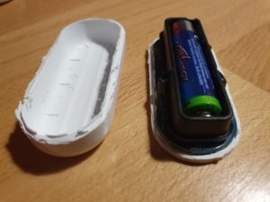
Nope..not working...of course the button forgot anything about WiFi and PWD. So I wanted to use the Amazon-App to save this settings.
Nope..not working..Amazon has changed the App, no menue-item any-more for Dash-Buttons. So, how to teach the button about the WiFi?
While doing research I learned more about this button, and had an interesting evening, starting here: https://github.com/danimtb/dasshio/issues/93
My “Dash-Button” is a little WebServer with Access Point!
During Reset the button opens it own WiFi AP, so you can access him via: http://192.168.0.1 from a browser of the device in this local WiFi. It tells you e.g. the firmware version. The button also allows to set-up the WiFi SSID and PWD with http://192.168.0.1/?amzn_ssid=SSID&amzn_pw=PASSWORD.
My “Dash-Button” can update its firmware and validates certificates!
Nope..not working.. this tiny buttons has a firmware, and when connected to the internet, it automatically updates the firmware (could you imagine, this little thing..). As of a recent version of firmware, that button wants to connect to an Amazon Server and is validating its certificate before he is saving the WiFi information. Amazon has disabled the server, because of the certificate validation you can not “fake” an Amazon server. No way to convince the button to save the SSID and PWD 🙁
So…is there a way to get an older version of firmware or maybe a firmware hack?
My “Dash-Button” has a microphone !
In case WiFi is not working, the Dash-Button can be configured using *sound*, so it has a little microphone and it will load its setting from the mobile via audio. Some really smart people found a memory leak in this interfaces and managed to use this leak to implement a new version of the firmware that would skip the certificate validation. I found this on github: https://github.com/znuh/dashbutton
So, you download the wave-file, reset-the button, play the wave-file and afterwards http://192.168.0.1/?amzn_ssid=SSID&amzn_pw=PASSWORD will work again, because the button will not ask for the certificate.
Trying it, it first looked great – the button reacted on the sound, but:
Nope..not working.. I found out, that my button had a recent version of the firmware and that Amazon has fixed this bug in the new version.
My “Dash-Button” gets a *Packet of Death* from Amazon!
I also learned that (at the moment) any Dash-Button now would connect to the internet, it will receive a special command to completely disable itself by going into an endless-loop.
Conclusion – The POWER OF AMAZON
I spent a full evening with my Dash-Button, a bit disappointing that I couldn’t get it back to live, but a very interesting learning experience.
How much effort and brain-power Amazon put into this button with a functionality that is completely invisible to the user – who only things he buys a button. And that has even a microphone. And also how much power does Amazon have, the company just decided that the buttons should not be used any-more, updates the firmware, sends a packet of death and disables the certificate server. Now you have just a peace of dead electronic to through away.
Makes me thinking….how much sensors and computing power is in a mobile phone or an robotic vacuum cleaners. And how much power do we have about this devices – if we even cant control a simple button 🙂
 Touchdisplay running on ESP8266 (Wemos) – RPI Remote Controll (22.09.2019)
Introduction
I am using a 1.8 Inch LCD Screen SPI Serial Port Module TFT Color Display Touch Screen ST7735 (128*160) for Arduino”, bought for 9€ from aliexpress.com.
Details: Display Processor: ST7735, Touch Processor: XPT2046, Display Type: ZJY180-TV2.0,128*160, as ESP8266 I am using the WEMOS D1 Mini Pro (v 2.0) https://wiki.wemos.cc/products:d1:d1_mini_pro.
Its part of my Project “BigPi” to use the PI4 as my central home server. I decided it needs a display.
Things should look nice..so what did I do?
Actually I got the Touchdisplay running at the RPI after a lot of tries – but what do I have on my desk: A big black RPI4 box with a touch-display. Not looking good.
My alternative: I build a tiny Touchdisplay with ESP8266 in a little box with battery, that I can place anywhere. I will communicate via WIFI to my RPI. No black box on the desk, just a cool multifunctional switch and status-display for RPI Remote control. Kind of a long running project – lets see how it goes.
Wiring – how to get it together
Of course, from china – there is not much documentation. Below some information I found at AliExpress about the display and all contacts at the display have labels. To note: PEN (11) is high, and gets low, when the display is touched – so can be directly linked to the Wemos (see below).
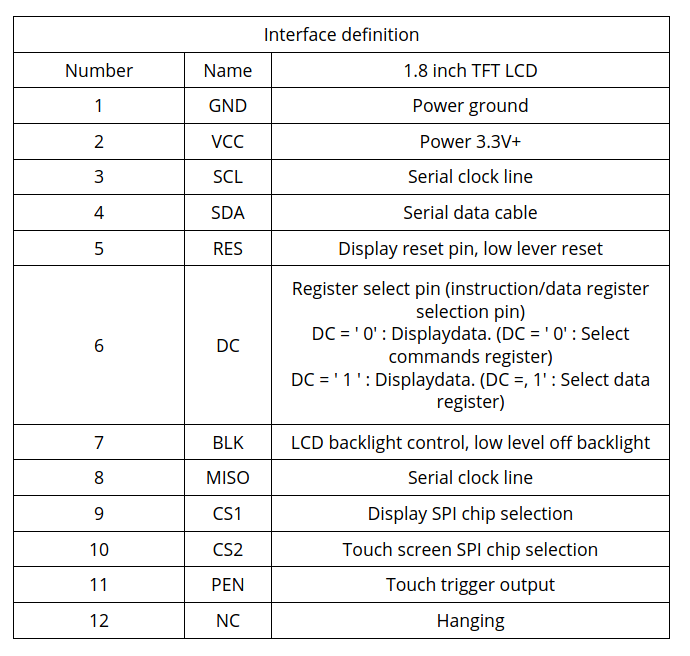
Information from Vendor 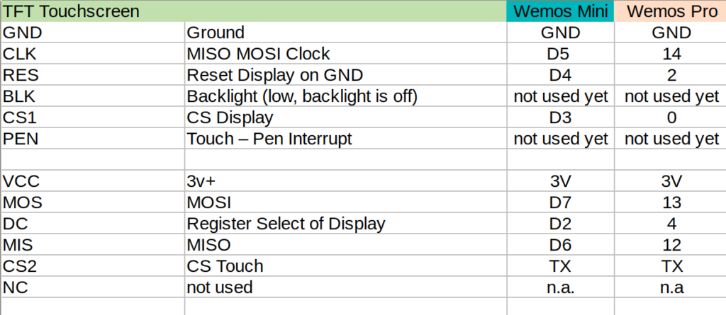
Mapping TFT Panel to Wemos Some Details about the WEMOS D1 Mini Pro
Understanding the Solder-Pads
This is a very nice ESP8266 processor, small size and including LiPo charger unit, so any 3.7V battery can be directly attached on it and can be charged via the mini USB. Its Pin-Compatible to the well known WEMOS Mini, that has some interesting soldering-pads on the back:
- SLEEP: This connect the Reset and the XPD_DCD – Deep Sleep Wakeup, so the WEMOS can waket-up itself from Deep-Sleep. For easy programming and the serial interface to work, this should not be connected. So do it, before you put it into production
- BAT-A0: Links the battery power to the analogue A0 input, so its possible to measure battery voltage (to detect low battery).
- LDO_EN: To disable the 5V regulator, so you can provide your own power source directly to the 3v3 and GND pins. Useful for battery operations. If you use standard lithium ion batteries that have 3.7-4.2V, it’s better to connect them to the 5V pin, since that is connected to an LDO converter.
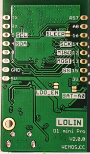
back side of the board Deep Sleep…tzzzzz…
I need “Deep Sleep” with ultra low power consumption, as it should run for a long time.
I measure current 0,15mA (150uA) out of the box for the WEMOS Pro Mini via the ESP.deepSleep(), with a 1200mAh LiPo it comes to 300 days.
If its running with display connected, but without backlight (BLK to GND), its consuming 0.48 mA (500uA) – what is approx 100 days runtime, 3 month is ok 🙂
When the display is active and backlight is on, it consumes around 20mA, when the display is off -it goes down to 1mA.
To Remember
During the Deep Sleep period GPIO_16 are held high. At the end of the Deep Sleep period GPIO_16 goes low, pulling down the Rest Pin (Reset Pin is low active, eventually add 1-10k resistor in between) and restarting the Wemos.
Prolem is, that when ESP8266 goes into DeepSleep, all IO are goint go High – so my display is “on”. It will need an inverter.
SPI – Confusion
SPI did confuse me, it has 3 lines MISO, MOSI and clock, the same I found on the touch-display. At the end I realized that it has 2 controllers, one for the touch sensor, and the other one for the display. Both are connected at the the same SPI bus and are selected based on chip select. So it somehow looks like below:
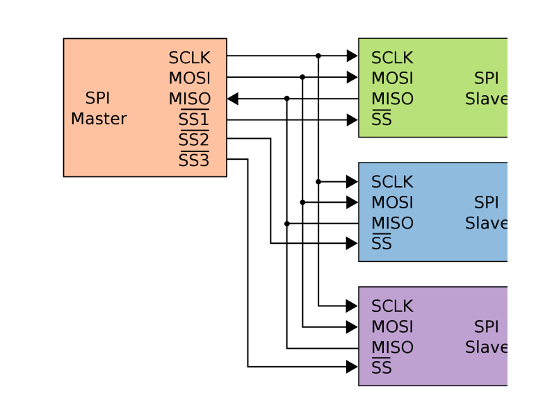
SPI Logic on the TFT/Touch Display
Software – How to get it running?
I am using CLION from JetBrains and Platformio for development -what I can really recommend to do. The following libraries support both controllers:
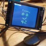
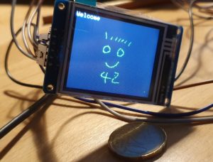
Adafruit ST7735 and ST7789 Library
Adafruit GFX Library
XPT2046_Touchscreen
Thanks to this great libraries, below makes you paint on the little display with a pen, just some lines of code.
void setup(void) {
tft.initR(INITR_GREENTAB); // initialize a ST7735S chip, CN: My-chip has a "green flag at the protection foil"
tft.setRotation(1);
tft.fillScreen(ST7735_BLACK);
ts.begin();
ts.setRotation(0);

delay(500);

tft.fillScreen(ST7735_BLACK);
testdrawtext("Welcome", ST7735_WHITE);
delay(1000);
tft.drawPixel(150, 118, ST7735_GREEN);

}

void loop() {

if (ts.touched()) {
TS_Point p = ts.getPoint();
tft.drawPixel(p.y * x_tft_scale, p.x*y_tft_scale, ST7735_GREEN);
}
delay(5);
}
Mission completed 🙂
 Migrating from MySQL to Postgres (25.07.2019)