Category: Archive

  • What Amazon Dash Buttons Teach About IoT Design

    What Amazon Dash Buttons Teach About IoT Design

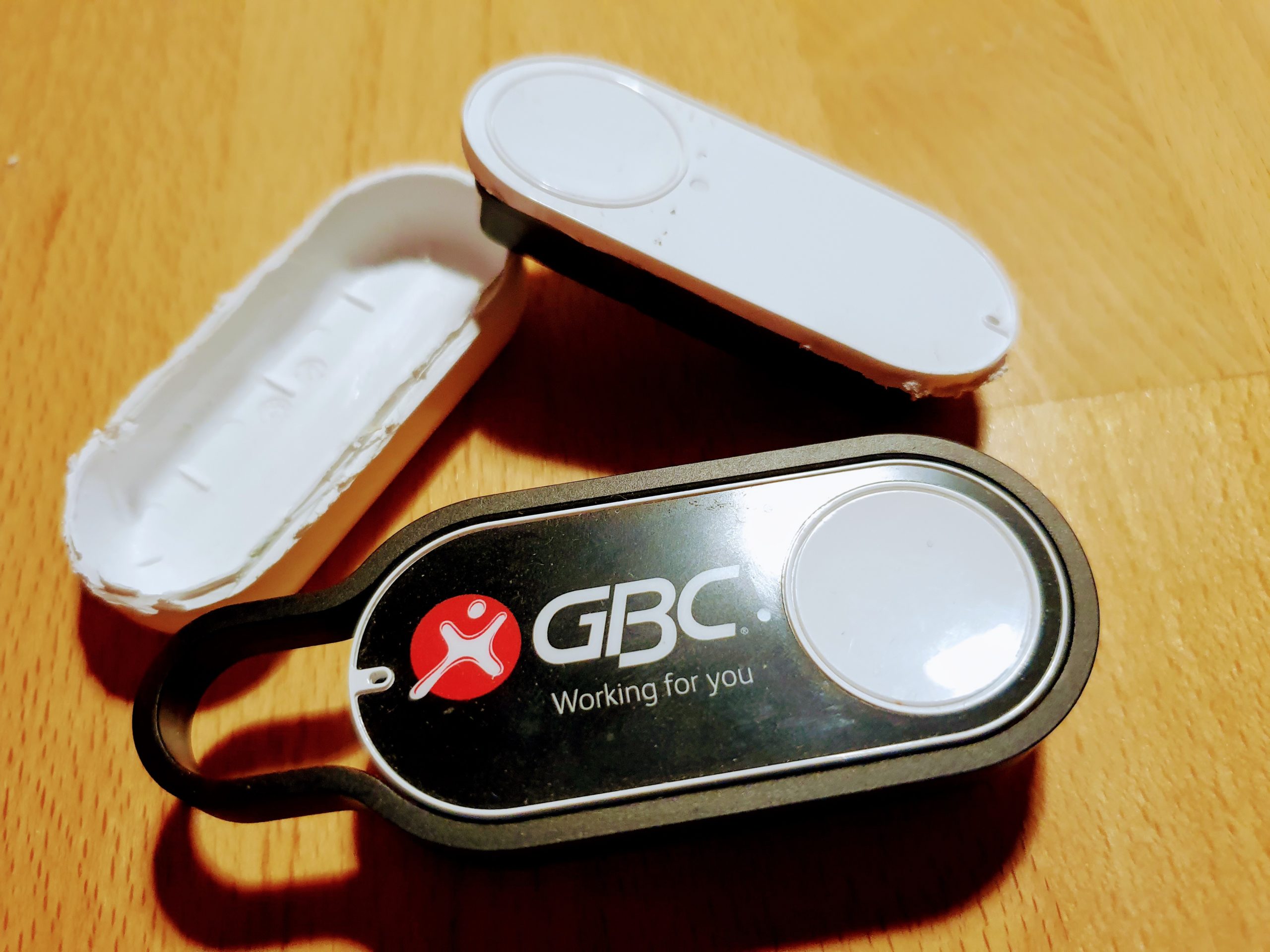
    I am using Amazon-Dash buttons in my home automation project, got them from eBay for some euro. So I can switch-off all lights and heating from my bed, dim the lights in the living-room when watching TVs. And all for nearly no money. The buttons a made for 1000 clicks, so I thought I would be save.

    But I didnt realize the “power of Amazon” and under-estimated the SW and HW that is build into this little button.

    My plan – how to use the “Dash-Button” in Home Automation!

    Amazon did everything to make the button not useable – except for ordering from Amazon 🙂

    But smart people found a solution: You set-up the button once with the Amazon App (to let him connect to your WiFi network by providing SSID and PWD) .

    When the button is pressed, it wakes up and needs to re-connect to the configured WiFi , this connection event can be monitored with a simple script to install on  RPI HomeServer with Openhabian: https://github.com/Nekmo/amazon-dash

    sudo apt-get remove python3-pip; sudo apt-get install python3-pip
    sudo pip3 install amazon-dash
    <code class="yml">sudo systemctl start amazon-dash 

    Finally you need to configure the buttons (name, mac-address)  to be controlled in a config-file That’s it – you can access the button from OpenHABian like any Hue device.

    Ohnn…not really…..its important you make it impossible for the button to “CALL HOME” to Amazon (e.g. with a FritzBox you disable internet for fixed IP address of the button).

    The big disappointment!

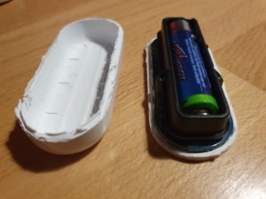
    One day, one button stopped working.It seems that the battery is empty. Ok, no problem – took me a while to open the case  – and I replaced the battery.

    Nope..not working...of course the button forgot anything about WiFi and PWD. So I wanted to use the Amazon-App to save this settings.

    Nope..not working..Amazon has changed the App, no menue-item any-more for Dash-Buttons. So, how to teach the button about the WiFi?

    While doing research I learned more about this button, and had an interesting evening, starting here: https://github.com/danimtb/dasshio/issues/93

    My “Dash-Button” is a little WebServer with Access Point!

    During Reset the button opens it own WiFi AP, so you can access him via: http://192.168.0.1 from a browser of the device in this local WiFi. It tells you e.g. the firmware version. The button also allows to set-up the WiFi SSID and PWD with http://192.168.0.1/?amzn_ssid=SSID&amzn_pw=PASSWORD.

    My “Dash-Button” can update its firmware and validates certificates!

    Nope..not working.. this tiny buttons has a firmware, and when connected to the internet, it automatically updates the firmware (could you imagine, this little thing..). As of a recent version of firmware, that button wants to connect to an Amazon Server and is validating its certificate before he is saving the WiFi information. Amazon has disabled the server, because of the certificate validation you can not “fake” an Amazon server. No way to convince the button to save the SSID and PWD 🙁

    So…is there a way to get an older version of firmware or maybe a firmware hack?

    My “Dash-Button” has a microphone !

    In case WiFi is not working, the Dash-Button can be configured using *sound*, so it has a little microphone and it will load its setting from the mobile via audio. Some really smart people found a memory leak in this interfaces and managed to use this leak to implement a new version of the firmware that would skip the certificate validation. I found this on github: https://github.com/znuh/dashbutton

    So, you download the wave-file, reset-the button, play the wave-file and afterwards http://192.168.0.1/?amzn_ssid=SSID&amzn_pw=PASSWORD will work again, because the button will not ask for the certificate.

    Trying it, it first looked great – the button reacted on the sound, but:

    Nope..not working.. I found out, that my button had a recent version of the firmware and that Amazon has fixed this bug in the new version.

    My “Dash-Button” gets a *Packet of Death* from Amazon!

    I also learned that (at the moment) any Dash-Button now would connect to the internet, it will receive a special command to completely disable itself by going into an endless-loop.

    Conclusion – The POWER OF AMAZON

    I spent a full evening with my Dash-Button, a bit disappointing that I couldn’t get it back to live, but a very interesting learning experience.

    How much effort and brain-power Amazon put into this button with a functionality that is completely invisible to the user – who only things he buys a button. And that has even a microphone. And also how much power does Amazon have, the company just decided that the buttons should not be used any-more, updates the firmware, sends a packet of death and disables the certificate server. Now you have just a  peace of dead electronic to through away.


    Makes me thinking….how much sensors and computing power is in a mobile phone or an robotic vacuum cleaners. And how much power do we have about this devices – if we even cant control a simple button 🙂


  • Migrating a Rails Application from MySQL to PostgreSQL with pgloader

    Migrating a Rails Application from MySQL to PostgreSQL with pgloader

    I am having some trouble on the RPI 4 to get Rails installed and finding the right version of MYSQL (MariaDB) and ActiveRecord while running an older version of Rails and a newer version of Sphinx (search index). Anyway I always wanted to move to PostgreSQL…thats the time to do.

    The tool of my choise: PGLoader

    I realized pgloader does not like to run on the RPI, but the solution is easy:

    SourceDB (Cubietrack) <-> Linux PC (my desktop) = Running PG-Loader <-> TargetDB (RPI4)

    I wanted to have the schema on the target-db, as original as possible for Rails, so I used rake:
    <br />
    rake db:create<br />
    rake db:schema:load<br />

    to have an original Rails DB set-up. PGLoader is used for data-migration.

    Script:
    <br />
    LOAD DATABASE<br />
    FROM mysql://export:xxx@ct/CTCD2Server_production<br />
    INTO pgsql://docbox:xxx@pi:5432/docbox_production<br />
    with data only<br />
    ALTER SCHEMA 'CTCD2Server_production' RENAME TO 'public';<br />

    Two important points:

    1. The last statement “alter schema” is important, as pgloader creates a schema with the same name as the source db and creates all table in this schema – and rails may not expect this.
    2. “with data only” – tells pgloader that the schema is already existing (rake db:schema:load)

    Once, I got the script working – data migration is just a “button press”.


  • LoRa

    LoRa – Washing and Parking

    What is LoRa?

    LoRa (Long Range) is a spread spectrum modulation technique derived from chirp spread spectrum (CSS) technology and is the first low-cost implementation of chirp spread spectrum for commercial usage.[1] It was developed by Cycleo of Grenoble, France, and acquired by Semtech in 2012, a founding member of the LoRa Alliance.(Wikipedia).

    What do I want to do?

    We have a Washing Machine in the basement – and allways forget when its finished. So I want to build a LoRa module, stick it to the Washing Machine.  A little sensor will check when it runs (by the movement). And when its finishing running (tumbling) – it will  notify me with OpenHab.  Aaah.. yes – and we have a garage (only 1 for 2 cars). So,  how to know, if its already used by one car. Also an idea for LoRa.

    Network Topology

    LoRa consists of 4 parts:

    1. Nodes: Endpoint, e.g. measuring device
    2. Gateways: Bridge between the note and the internet, the number of channels that a gateway has is the number of nodes that it can talk to at once, node is not sending allays, e.g. a 1% duty cycle represents almost 15 minutes of combined
    3. Network Servers: direct packets between gateways and application servers. Since LoRaWAN™ allows for uplinks (messages to a server from a node) and downlinks (messages to a node from a server).
    4. Application Servers: Does actually do something with the data.

    I will try first to get a P2P communication running, meaning just connecting 2 LoRa Endpoints calling Client and Server

    Client and Server

    As the “LoRa Server” I plan to use an ESP8266 (with WIFI) – to connect to RFM95.

    As the Client I want to use a module (ready made) you can by in china for cheap money: LoRa Radio Node v1.0.

    For both I will use the the LoRa-Library from Sandeepmistry.

    The nifty Details

    Server: ESP8266 with RFM95

    The RFM95 Device
    1. Frequency used in Germany: Frequency Plan: EU863-870, 868 Mhz,  you must use at least the 3 main channels you already mentioned (868.1, 868.3 & 868.5) with a duty cycle of <1%
    2. Device used: RFM95 868 MHz (my one does not have a “W” – RFM95 vs RFM95w)
    3. Antenna:cut a stranded or solid core wire the the proper length for the module/frequency: 868 MHz – 3.25 inches or 8.2 cm ((How to connect the antenna)

    These different transceivers are using Semtech SX1276 chip.

    The configuration and communication of the module is done via 4-wire SPI Bus, technically implemented in all microcontrollers.

    RFM95 Documentation

    1. ANT is the antenna Pin.
    2. GND can be connected to any of the GND pad (connecting all is always better)
    3. DIO0 is used by RFM95w module to trigger RxDone/TxDone status.
    4. DIO1 is used by RFM95w module to trigger RxTimeout and other kind of errors status.
    5. NSS, MOSI, MISO, SCLK are for SPI communication. NSS is the chip select signal. Arduino is the master.
    6. Reset is resetting the RFM95w module.
    Wiring

    see gallery below for mapping RFM95 with ESP.

    Serial interface and  does not work, when pin 2 is connected. Pin can be connected after serial starts working.

    Client with LoRa Radio Nove v1.0

    As “LoRa Client (the module that is sending data, form a sensor) I am using the  LoRa Radio Node v1.0

    1. Power supply: 3.7V 14500 Lipo battery Or 3.7-12V DC power(VCC GND: 2PIN 2510-I Type connect) and 3.3V regulator with 500mA peak current output
    2. ATmega328P @ 8MHz with 3.3V logic/power, 32K of flash and 2K of RAM, same usage as Arduino pro mini.
    3. Hardware Serial, hardware I2C, hardware SPI support
    4. 1 x PWM pins: D3
    5. 2 x analog inputs: A0 A1
    6. Pin #13 BLUE LED for general purpose blinking
    7. Reset button

    LoRa Radio Node v1.0 1

    Wiring

    Nothing to wire at all. Connect Antenna, put in a 3.7V LiI-Ion Battery (e.g. Model 17500, 3.7V,850mAH) for operation and use a standard FTDI cable to program and test.

    Pin Mapping between RFM95 and ATmega328P:

    RFM_DIO0 = 2
    RFM_NSS  = 10
    RFM_RESET 9

    The ATMega and the RFM95 will be sent to Deep-Sleep to save power. Wake-up is possible via connecting RESET to GND.

    First Results

    Distance:  Amazing, 3 level building with thick walls down into the cellar – still working.  RSSI values from -23 (when close to together, down-to -99 on some distance). I am impressed by LoRa technology. It works for my use-case 🙂

    Power-Consumption – Sending: A lot when sending – but only on peek times.

    Power-Consumption – Sleeping: Using DeepSleep Library and sending the RFM95 via LoRa.sleep results in  0.08mA to 0.1mA, providing nearly a year of runtime with a 850mAh battery. Perfect

    Detailed Pictures (click to enlarge)