Category: Embedded and Physical Computing

  • Pigeon Wars: When a Balcony Problem Becomes Edge Computing

    Pigeon Wars: When a Balcony Problem Becomes Edge Computing

    We have a balcony. It has a fig tree, some tiles, and pigeons. Every time I spotted one I’d rush out and wave my arms. They came back ten minutes later. So naturally, as a tinkerer, I thought: let’s automate this.

    The idea was simple — a small camera, an ESP32, detect movement, send a photo. A few evenings of work. That was a year ago.


    The Battery Problem Ate Everything

    The motion detection worked fine. Then night came. Battery dead by morning.

    Most ESP32 dev boards look great on paper — deep sleep, LiPo charger, low power modes. What the specs don’t tell you: the camera module keeps drawing current even in deep sleep. I tried transistors to cut power. MOSFETs. A second microcontroller to switch the main board off. Each solution either drew too much standby current or added complexity that broke something else.

    The fix was radical: cut power entirely between events. No deep sleep. The hero component is the TPS22918 — a tiny load switch IC. The PIR sensor triggers it, which cold-boots the ESP32-S3 from zero. First firmware instruction self-latches the power rail. Job done → board releases the latch → fully dark. Standby current: ~140 µA, mostly the PIR sensor itself. The ESP32 draws nothing, because it has no power. If there is time, I will write a more detailed article on this topic – it was a bit of a challenge to find out the right part and to get the tiny smd part soldered, but its just perfectly running after all my other failed hardware attempts. 🙂

    Yes, that’s a breadboard in a cardboard box. It’s a prototype.


    WiFi Shoots the PIR. Literally.

    Just when power felt solved: WiFi radio interference was triggering the PIR sensor during uploads. The system went haywire — blinking, re-triggering, spiralling. Took a long time to find. The fix: disable the PIR interrupt during WiFi transmission, handle re-triggers gracefully.


    AI vs. Algorithm — The Surprising Part

    The balcony has plants, a railing, and a sky. At noon the sun triggers the PIR constantly — clouds moving, shadows sweeping. Most captured photos were empty.

    The obvious answer in 2025: throw a neural network at it. I went the other way — a classical signal-processing filter that runs on the ESP32 in under 10ms, before WiFi even wakes up. It tiles the frame into a grid, compares each tile against a self-learned per-time-of-day background, and decides: real event or just clouds?

    Tested on 147 field captures: 100% recall on real events, 61% of false triggers suppressed. No training data needed. No model file. Self-calibrates from live captures. Fits in 2 KB.

    Sometimes the old tools are the right tools.


    Where It Stands

    The platform is solid — reliable wakeup, false-trigger filtering, photo upload. What’s still missing: the cloud-check filter needs porting from Python to C on the ESP32, and the ESP32-S3 has enough headroom for a small TFLite model — so the hardware is already ready for on-device bird detection, even if the pigeon-brain isn’t written yet.

    The pigeons may well have died of old age before I finish. But I learned more about embedded hardware in this project than in anything before it. Respect for people who build systems that run outdoors, unattended, for months — that respect has gone way up.

    Code: github.com/happychriss/birdwatch-edge-platform

  • ESP32 Soundbox in an IKEA Frame: A Weekend Hardware Build with AI Support

    ESP32 Soundbox in an IKEA Frame: A Weekend Hardware Build with AI Support

    A friend of mine has a very particular taste in music. So when our group decided to give gifts that all fit into a common frame — literally — I had an idea. Why not build an actual sound machine inside an IKEA picture frame? Total budget: under €30, one weekend, and one AI coding assistant. Let’s go.


    The Hardware

    I didn’t have much time, so I just ordered everything from AliExpress in one shot:

    • Ai-Thinker ESP32-Audio-Kit (ESP32-A1S V2.2) — ESP32 with onboard ES8388 audio codec, two NS4150 class-D amplifiers, SD card slot, Bluetooth, six hardware buttons, all in one board. About €17.
    • WS2812B LED strip, 30 LEDs — individually addressable RGB, wired to GPIO22. Around €4.
    • Two small speakers from my parts bin.
    • A 5×7″ IKEA picture frame — €5.
    • A USB power cable for 5V supply.

    That’s it. No custom PCB, no breadboard rats’ nest. The board has two USB connectors — one for flashing, one for power — which makes things even cleaner.

    The speakers sit inside the frame glued to the plastic backing. If I were to rebuild this, I’d attach them directly to the wooden frame itself so it acts as a resonance body — the 6W amplifier is there, the 4Ω drivers are there, but right now the sound escapes through plastic. It still sounds surprisingly good for five-euro speakers. With the frame as resonator it would be genuinely excellent.

    The Build

    Everything fits together with double-sided tape and a hot glue gun. The only soldering needed is:

    1. Speaker wires to the board’s JST connector pads
    2. LED strip power + signal wire to the board

    The board is recessed slightly into the back of the frame so nothing sticks out beyond the frame depth. You can hang this directly on a wall.

    One small thing I’d add next time: an external power switch. Right now you unplug it. Works fine, but still.

    What It Does

    The feature set ended up being pretty complete:

    • Plays all .mp3 files from the SD card root in alphabetical filename order, looping forever
    • _welcome.mp3 always plays first on boot (underscore sorts before letters) — the box greets you with a purple light frame
    • KEY1 short-press: pause/resume
    • KEY1 long-press (2 s): toggle Bluetooth A2DP sink mode — LEDs pulse blue during pairing, then your phone streams audio through the same codec and the same LED show
    • KEY3/KEY4: previous/next track
    • KEY5/KEY6: volume down/up
    • Bluetooth device name: Dietmars-Soundbox (personalized gift, obviously)

    The LED Show

    This is where it gets technically interesting. The LED task runs a 5-layer composited show on Core 0:

    1. Ambient — slow color breathing based on overall volume
    2. Beat burst — flash on kick detection
    3. Bass blob — low-frequency energy mapped to brightness
    4. Sparkles — random high-frequency glints
    5. Picture frame — the four sides of the frame each get a distinct hue, driven by volume tier

    The audio pipeline works like this: PCM samples are tapped from the I2S write callback (both in SD and Bluetooth mode), converted from stereo int16 to mono float, and pushed into a stream buffer. The LED task drains that buffer, runs a 512-point FFT with a Hann window, splits the result into 8 logarithmic bands from 60 Hz to 20 kHz, applies per-band AGC with a ~10 s time constant, and does beat detection via a dual-EMA sub-bass ratio: kick_fast / kick_slow > 1.3, with a 200 ms minimum gap between beats.

    At quiet passages the frame breathes in calm colors at low saturation. Loud and fast music triggers full-saturation disco snaps where each side of the frame gets a randomly assigned hue with ~80–120° forced separation — so you never get two sides the same color by accident. Volume tiers (quiet / mid / loud) control how many frame sides are lit at once.

    It genuinely sets the mood of a room. That part was satisfying to see work.

    Building It With Claude Code

    I had a Docker container from a previous project — Ubuntu base, Node.js, @anthropic-ai/claude-code installed, USB serial device passthrough configured via docker-compose.yml. I dropped all the AliExpress datasheets and board schematics I could find into an external-docs/ folder, wrote a rough requirements.md, and let Claude loose.

    The setup is worth describing: the repo has a CLAUDE.md that tells Claude to read requirements.md, all skills/ files (working conventions per concern), and all knowledge/ files (validated config notes per component) at the start of every session. This way Claude has context persistence across sessions without relying on conversation history. Each time Claude confirms a working configuration, it writes a note into knowledge/ — so the next session starts with what was already proven to work.

    The first challenge was getting audio out at all. The ES8388 codec is sensitive to init order: SD card must mount before I2S init (GPIO25/26 conflict), MCLK must be stable for 100 ms before codec init, and you must use I2S_CLK_SRC_DEFAULT — APLL causes broadband white noise on ESP32. Claude worked through all of that by trying, failing, reading the error, and adjusting. The right path was to use espressif/esp_codec_dev and never write ES8388 registers directly.

    There was also a nasty bug where every song with embedded cover art crackled at the start. The cause: the ID3v2 tag can contain a several-hundred-KB JPEG, and the Helix MP3 decoder was scanning through it byte-by-byte looking for a sync frame, starving the I2S DMA buffer. The fix was to parse the syncsafe size from the ID3v2 header and fseek() past the entire tag before handing the file to the decoder. Claude found this independently after I described the crackling symptom.

    Bluetooth required a custom 3 MB partition table because the BT stack pushes the binary to ~1.1 MB. The A2DP data callback must be strictly non-blocking — push to a StreamBufferHandle_t, drain on a separate task on Core 1 — otherwise you drop the BT link under any load.

    I’m a decent programmer. I would have needed two or three weekends to get all this working on my own. With Claude Code it was one.

    Bill of Materials

    PartCost
    ESP32-Audio-Kit (A1S V2.2, ES8388)€17
    WS2812B LED strip (30 LEDs)€4
    IKEA picture frame€5
    Misc (USB cable, tape, glue)~€3
    Total~€29

    Speakers from the parts bin, SD card from a drawer. Add another €5 if you’re buying those.

    What’s Next

    The natural upgrade is a small 5V LiPo under the frame for wireless wall-hanging. The LED strip needs 5V anyway, so no boost converter required — just a tiny LiPo with a TP4056 charger board under the frame. And a proper external power switch.

    Full source and the devcontainer setup are on GitHub.


    A few things I took away from this: cheap AliExpress hardware is genuinely capable if you understand what you’re buying. The ES8388 codec is a real audio chip — it sounds good. And Claude Code is a legitimately useful tool for embedded work, not just web stuff, as long as you give it structured context. The knowledge/ folder approach — where confirmed hardware facts accumulate across sessions — made a real difference. It’s worth setting up properly.


    GitHub: happychriss/ESP32-A1S-sound-machine

  • ESP32 Boot Optimization with PlatformIO and Menuconfig

    ESP32 Boot Optimization with PlatformIO and Menuconfig

    Speed Up Boot-Time with Menuconfig (ESP32)

    When you read this, you may have been already going a long way … and I am still walking.. so this is just my latest understanding. Feel free to correct and help me to further detail this out – and be ready that not all below is really correct… but at least … I got it working this way.. 🙂

    Why does it take a second to boot?

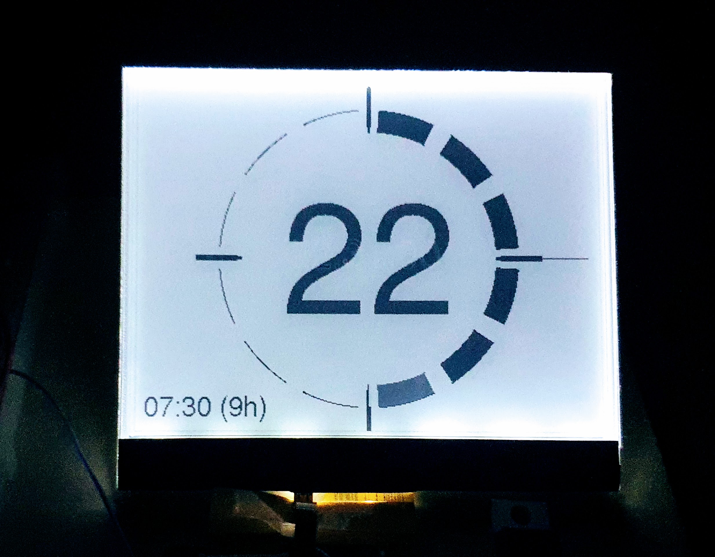
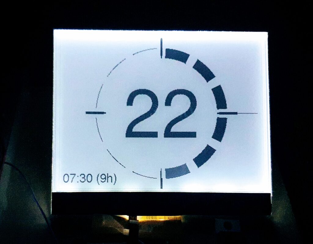
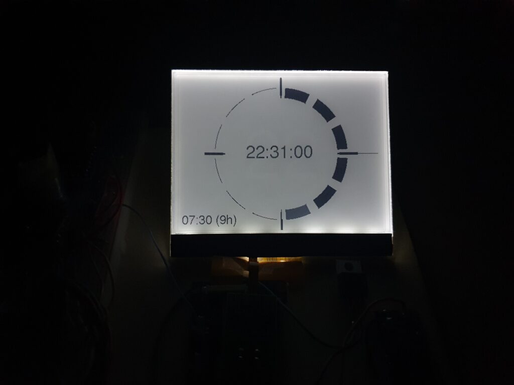
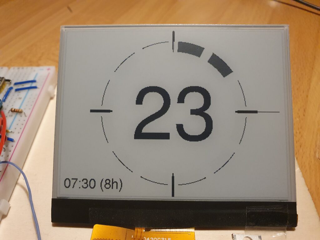
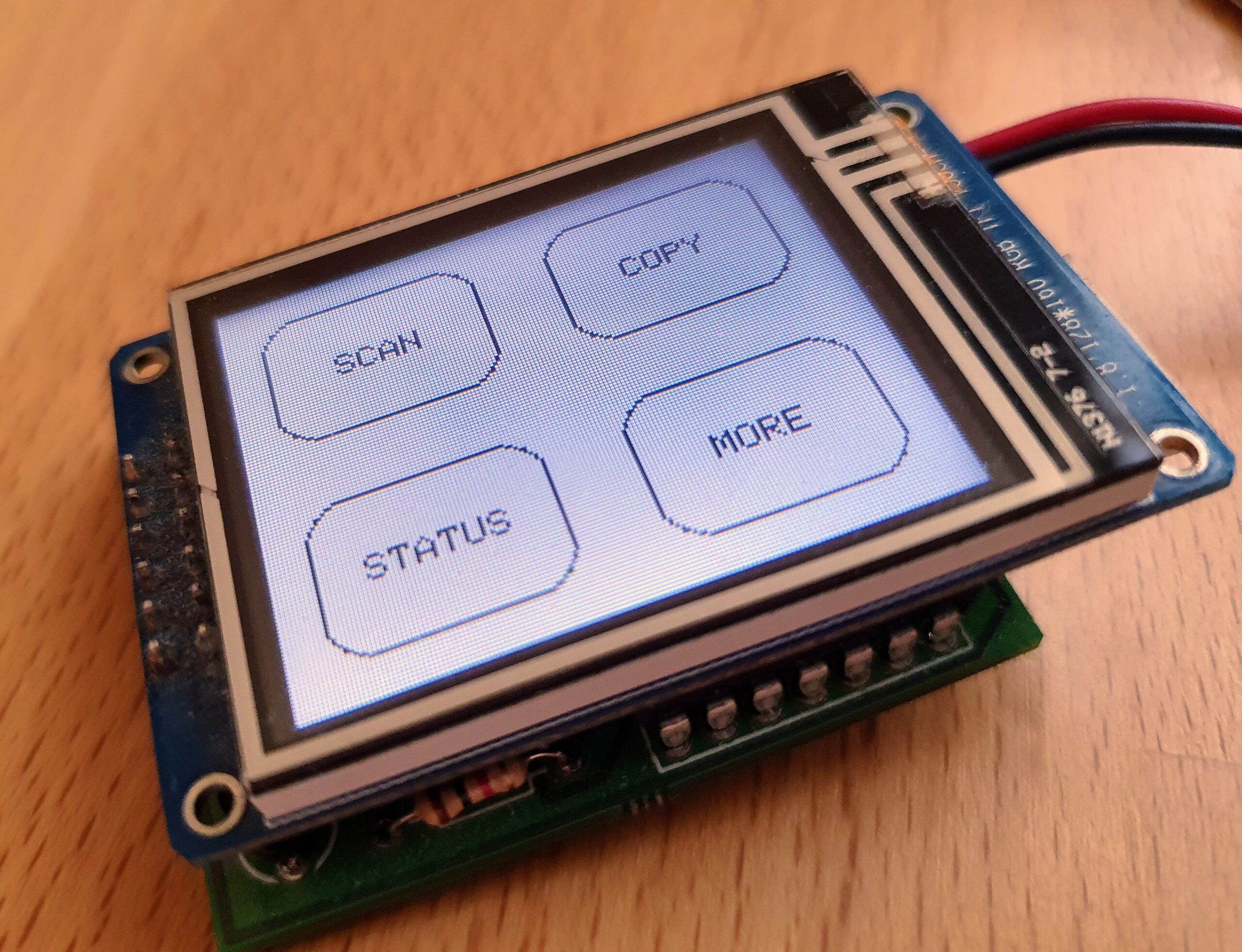
    Boot-Time becomes critical for any embedded device, when you need wake-up from deep sleep and immediate action.  I needed a short boot time  for the Goodwatch project, to make sure the clock is awake super fast when I want her to show the time in seconds on a “hands move” (watch the video here.).

    On the  Wemos D32 Pro it took approx 1 second to  boot – that is to long for many tasks.

    During this 1 second the processor e.g. runs some selfcheck for ram (PSRAM) and some other stuff.

    So – I was thinking, how can I skip this?

    If you ever looked at your PC BIOS you could see some options there, something similar exists for the ESP32: Menuconfig is a configuration utility provided by Espressif to fine-tune settings for the ESP32 processor family – looking a bit like BIOS settings:

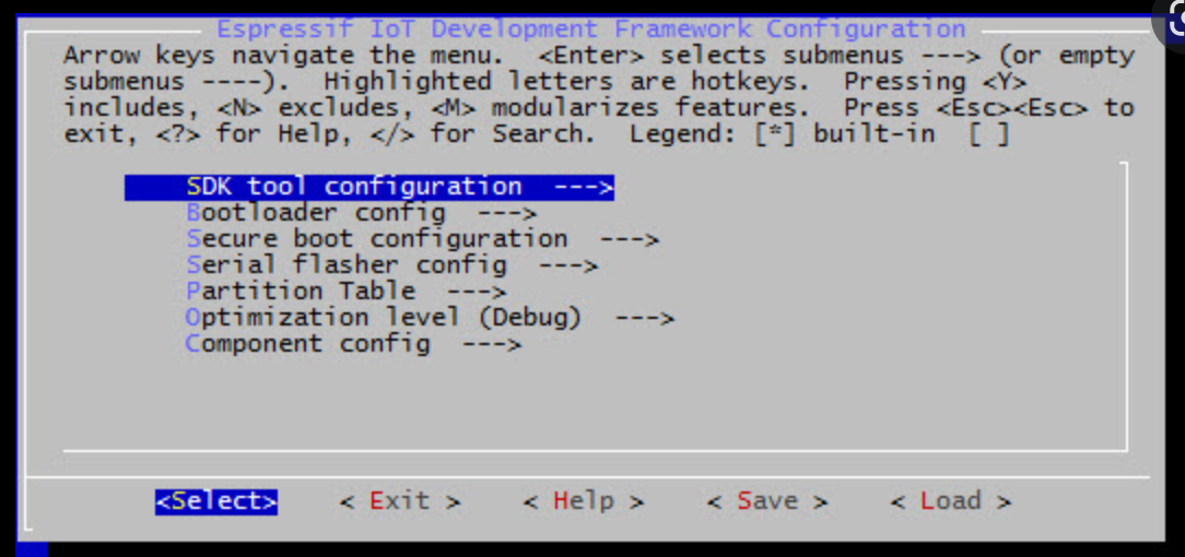
    But with menuconfig you can do much more, so – what I did for Goodwatch

    • Speedup boot as described in : https://esp32.com/viewtopic.php?t=9448
    • Support for external RAM: Y
    • Run memory Test on SPI Init: N
    • Faster SPI: Serial Flasher Config” QIO
    • Double Flash Read Speed: Set CONFIG_ESPTOOLPY_FLASHFREQ to 80 MH from Serial

    As a result, the boot-time reduced dramatically – seconds now are displayed nearly instant 🙂

    But here comes my problem – I did not manage to get menuconfig installed and working together with my Arduino build system and libraries….

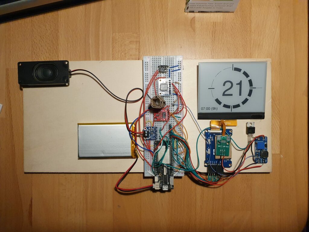
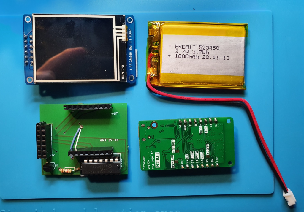
    I am using an e-Ink display and quite a few sensors – so it is great to have access to all the Arduino libraries  – just thinking about  ESP-Audio from Schreibfaul that converts the ESP into a radio or voice speaker are  worth using  Arduino, also the great e-Ink library from ZinggJM.

    Understanding the Build System and “Frameworks”

    Setting up that build system is complicated task. To build the Arduino projects I am using Platformio.io – a build and development platform for embedded devices, that supports Arduino but also many other frameworks.

    It helps to understand this terms:

    • Framework: Arduino or espidf: what type of libraries are used to communicate with the hardware. That is the most foundational decision.
    • Platform: That is the core from Platformio – a set of scripts, files that do all the hard work and set-up the build system for you. The platform determines which version of the
    • Components: Code blocks that can be added to the framework to extend the functionality (libraries). Arduino can be used as a component.  Arduino specific Components (libraries wrapping ESP calls into Arduino) are provided by ESP-IDF here. and can be addded here

    The default Platformio configuration is stored the platformio.ini for a simple “Arduiono” project is set-up like this:

    platform = espressif32
    board = lolin_d32_pro
    framework = arduino

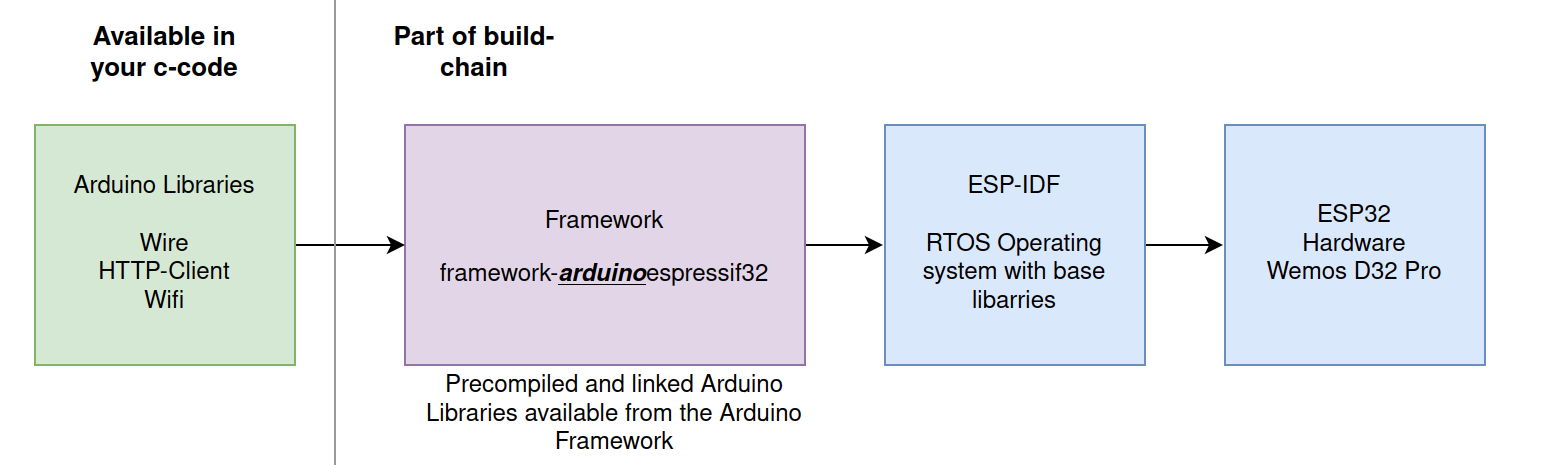
    The arduinoespressif32 Framework does all the work – it allows the device independent Arduino libraries to access the device specific ESP-IDF and ESP32 hardware functions.

    When running the build with Platformio you see the following:

    PLATFORM: Espressif 32 (5.1.1+sha.4901957) > WEMOS LOLIN D32 PRO
    HARDWARE: ESP32 240MHz, 320KB RAM, 16MB Flash
    DEBUG: Current (cmsis-dap) External (cmsis-dap, esp-bridge, esp-prog, iot-bus-jtag, jlink, minimodule, olimex-arm-usb-ocd, olimex-arm-usb-ocd-h, olimex-arm-usb-tiny-h, olimex-jtag-tiny, tumpa)
    PACKAGES: -framework-arduinoespressif32 @ 3.20004.220825 (2.0.4) 

    It using a version 2.04  of arduinoespressif32 , for ease of all the developers this is a “precompiled/bundled” version that does not need the full ESP32 build-chain to be installed.

    That explains, why menuconfig doesn’t work, it is changing the settings in the framework.  This is great to kick-off development (no issues with matching versions) – but there is  no way to change any settings 🙁

    Escape the cave – using ESP Framework with Components

    The only way to get menuconfig working and to have full access to all the ESP32 feature is moving to the Espressif IoT Development Framework. This comes direct from the vendor and allows configuration of the build-chain with menuconfig.

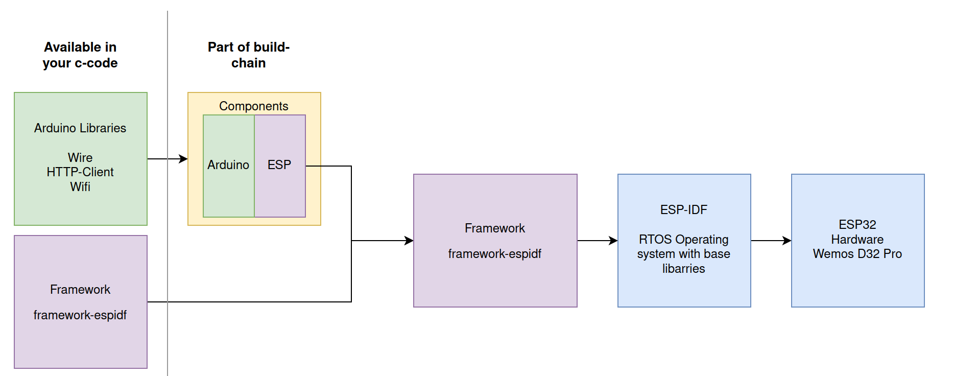
    To keep the best of both worlds, we must still use the Arduino libraries by adding them as Components. How this works is described here. In nutshell the project is not set-up using the Arduino build system and approach, but as the full Espressif chain.

    A folder “components” contains the libraries that map Arduino into ESP32 “language”. All Arduino libraries will keep working, calling the ESP32 functions via the components wrapper  – that call the core esp-functions.

    The challenge – the matching game & magic of Platformio

    But now –  at the end, all must match: Arduino version -> Component -> Espressif Framework… here the nightmare starts…

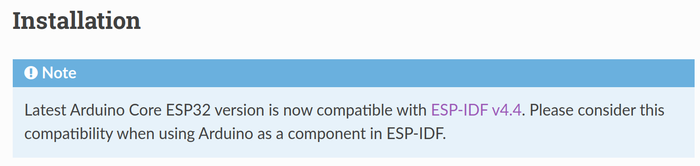
    Espressif already gives an important information and provides the component at this page.

    The components can be installed from here: https://github.com/espressif/arduino-esp32.git

    It also says the work together with ESP-IDF v4.4.

    Now we need to find the matching framework from espidf that supports ESP-IDF v4.4

    First Option – Just try the Standard

    So – lets update platformio.ini with the espidf framework. Should work, we have the components ready

    framework = espidf
    platform = espressif32
    board = lolin_d32_pro

    Result:

    PLATFORM: Espressif 32 (5.1.1+sha.4901957) > WEMOS LOLIN D32 PRO
    HARDWARE: ESP32 240MHz, 320KB RAM, 16MB Flash
    DEBUG: Current (cmsis-dap) External .....
    PACKAGES:  - framework-espidf @ 3.40401.0 (4.4.1) 

    Ups…this didn’t work – its building for the ESP-IDF 4.4.1, and that is not aligned with our components. At the end of the build we get an error message: “undefined reference to `uart_get_tx_buffer_free_size’”

    Second Option – Pick the right platform for IDF v4.4
    framework = espidf
    platform = https://github.com/platformio/platform-espressif32/archive/refs/tags/v4.4.0.zip
    board = lolin_d32_pro

    This looks better, we are now at ESP-IDF 4.4.0

    PLATFORM: Espressif 32 (4.4.0) > WEMOS LOLIN D32 PRO
    HARDWARE: ESP32 240MHz, 320KB RAM, 16MB Flash
    PACKAGES:  - framework-espidf @ 3.40302.0 (4.3.2) 

    Arrgh..but another error-message:

    Arduino-esp32 can be used with ESP-IDF versions between 4.4.0 and 4.4.99,
    but an older version is detected: 4.3.2

    That’s strange, also the platform version indicates using 4.4  –  it seems that the framework selected  remains still on 4.3.2 level  – that is not matching to our components

    Third Option – Using the Tasmota Platform

    Cant remember anymore where I found that tip -but it saved my live. Tasmota is so kind of providing another platform file for Platformio that works. Many thanks to Jason2866 (who maintains this at Github) for all his work – he really makes this possible!!!!!

    framework = espidf
    platform =https://github.com/tasmota/platform-espressif32
    board = lolin_d32_pro

    The result looks better:

    PLATFORM: Espressif 32 (2.0.4) > WEMOS LOLIN D32 PRO
    HARDWARE: ESP32 240MHz, 320KB RAM, 16MB Flash
    PACKAGES:  - framework-espidf @ 3.40403.0 <strong>(4.4.3) </strong>

    The “2.0.4” is the Tasmota versioning of the Platform-File (not the ESP-IDF version).But we see happily a framework with 4.4.3 selected. Hurray!!!!!!

    Honestly I do not understand the full magic in the Tasmota Platform configuration…. lets see what we have

    Deep Dive.. what is different from Tasmota to Platformio platform file

    Each platform file has a json, that defines the elements to be used for the build chain.

    Lets look at this file:

    "version": "2.0.4+1",
      "frameworks": {
        "arduino": {
          "package": "framework-arduinoespressif32",
          "script": "builder/frameworks/arduino.py"
        },
        "espidf": {
          "package": "framework-espidf",
          "script": "builder/frameworks/espidf.py",
          "description": "ESP-IDF is the official development framework for the ESP32 and ESP32-S Series SoCs.",
          "homepage": "https://docs.espressif.com/projects/esp-idf/en/latest/esp32/",
          "title": "Espressif IoT Development Framework"
        }
      },
      "packages": {
        "framework-arduinoespressif32": {
          "type": "framework",
          "optional": true,
          "owner": "tasmota",
          "version": "https://github.com/tasmota/arduino-esp32/releases/download/2.0.4.1/framework-arduinoespressif32.tar.gz"
        },
        "framework-espidf": {
          "type": "framework",
          "optional": true,
          "owner": "tasmota",
          "version": "https://github.com/tasmota/esp-idf/releases/download/v4.4.3/esp-idf-v4.4.3.zip"
        },

    What can we see here?

    • The “version” 2.0.4 seems to be Tasmota specfic and does not indicate the ESP-IDF version
    • The Tasmote package supports two framewors: “Arduino” and “espidf” – we look for espidf
    • The  framework-espidf framework points indead to a specific framework from tasmota with version 4.4.3  -> and that is the trick: Tasmota build its own framewor.
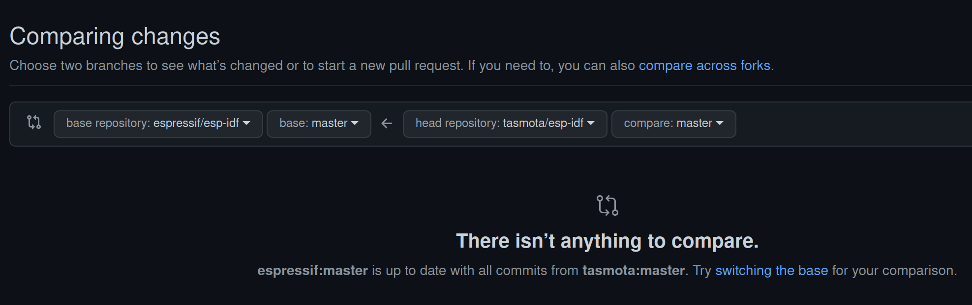
    • Looking at the framework form Tasmota here: https://github.com/tasmota/esp-idf we see its a fork from espressif/esp-idf version 4.4.3.
    • Comparing both forks I see they look the same. So I guess the differences between the Tasmota package and the Platformio Package are minimal, eventually just the version settings in the json.file

    Thats enough for me – now I have an easy config working 🙂

    How to do it – Tips & Tricks

    This is not a tutorial how to set-up the full build environment. So, to get there:

    1. Setup a normal development project with Platformio and following platformio.ini:
      framework = espidf
      platform =https://github.com/tasmota/platform-espressif32
      board = lolin_d32_pro
    2. Add the matching components from espidf to the folder structure as desribed here:https://espressif-docs.readthedocs-hosted.com/projects/arduino-esp32/en/latest/esp-idf_component.html
    3. I am running Platformio in CLION and get not working cmake file genertated after pio init. I use the following “CMakeLists.txt”:
      cmake_minimum_required(VERSION 3.16.0)
      include($ENV{IDF_PATH}/tools/cmake/project.cmake)
      list(APPEND EXTRA_COMPONENT_DIRS arduino)
      project(GoodWatch_espif)
    4. Run platformio build

    Long story … short… but works 🙂


  • TinyML on NDP101: A Practical Edge Impulse Development Setup

    TinyML on NDP101: A Practical Edge Impulse Development Setup

    In this short post I summarize my development environment using Platformio & Clion. I have adjusted platformio.ini file to include libraries and files needed – so you can start. EdgeImpulse provides a similar setting that fits when you are working with the Arduino IDE.

    Background

    I am using Platformio as development platform for embedded projects and CLION as my IDE. Both are integrated and together they provide a consistent way for programming, compiling and deployment – independent from the MCU/CPU used. I try to use the Arduino Libraries- as to a certain degree the provide platform independence. In addition many libraries are available for Arduino. To facilitate the Machine Learning I rely on Edgeimpulse – an cloud platform that supports the e2e machine learning cycle – so in a nutshell:

    • Platformio – Platform for embedded development
    • Clion – Integrated Development Environment with Platformio Integration
    • EdgeImpulse – Development platform for machine learning on edge devices

    The magic salt in the soup: EdgeImpulse

    EdgeImpulse takes away the two most complicated parts: The model design/training and the feature extraction. Its a science on its own to run a continuous inversion process on an small MCU (e.g ESP32) that includes recording the voice, running a Fourier transformation, applying a MEL transformation and finally to feed the features into the model. As the feature extraction during training (running on the cloud or on a desktop PC) and later during inversion (running on the ESP) must follow the exact same rules from logic AND timing persective- this adds additional complexity for embedded ML projects. Syntiant has partnered with EdgeImpulse – so the feature extraction and inversion process has been tailored for the NDP 101 – there is no need to deep dive into its architecutre.

    So..what do I get and how do I build actually something?

    Once training is completed (Detailed description from EdgeImpulse) EdgeImpulse gives you two options to download the software on your device: You can directly download a binary image and test your model, or – and here its getting really interesting – to download source code that contains:

    • Feature Extraction SW (DSP…)
    • Trained Model
    • Model Inversion (feed feature into model and run the inversion)
    • Library to integrate the “model decision=inversion result” into the c-code
    • Example program using all above based on Arduino framework – actually showing its working
    • For NDP101 it also contains the libraries to directly communicate to the NDP101 via SPI commands (load model, run model…..). I am still exploring the different commands and options

    SourceCode – Ready To Go Package on GitHub

    My initial template version for this configuration is available on GitHub https://github.com/happychriss/Goodwatch_NDP101_SpeeechRecognition

    To build this I have downloaded the Syntiant/EdgeImpulse repository and adjusted the file structure to the Platformio build system, in addition I have adjusted the platformio.ini file to include needed libraries.

    Please note that you will need to patch one of the libraries, the baseline for my work and also instructions how to patch the local libraries can be found here.

    A nice goody is the script download_model.sh – that connects to EdgeImpulse downloads a *build* model and puts the files in the right folders (./src/edgeimpulse) – so you can build your binary fresh from the model and upload to the board. You have to add a run-configuratio in CLION, so you can start the script directly. The API code for authorization on EdgeImpulse needs to be added to the paramerters.

    This is, how it looks like – when all is set-up. Enjoy developing.

  • Syntiant NDP 101 – Always-On Low Power Speech Recognition

    Syntiant NDP 101 – Always-On Low Power Speech Recognition

    NDP 101 – fresh from Digitkey – what do I want to now?

    I will integrate the Syntiant TinyML NDP101 board with my latest project: GoodWatch – a super smart voice controlled watch.

    Currently for GoodWatch I am using an ESP32 as MCU for speech recognition. It is working with 10 numbers and two keywords (yes, no). But – to get good results for so many keywords and to get a quick response – I needed to trick a bit: Its only listening to my words. If you want to learn more on ML for Edge-Device, have a look at: Overview of ML on Edge – Devices .You can see how far I got with an ESP32 here:Goodwatch: An eInk Alarm Clock That Tries to Understand Me

    With this project I have two objectives:

    • Wake up the alarm clock with a key word to set-up the Alarm, get it on 100% voice controlled operation
    • Enable speech recognition not only for my voice and reach a highly reliable speech recognition (otherwise setting up the old clock will be faster 🙂

    Some facts on the TinyML Development Board

    Board Overview

    I have ordered the development “Syntiant TinyML”, it is a combination of the NDP101 processor combined with a Cortex-M0+ 32bitARM MCU, a SPH0641LM4H microphone, a LIPO power connector and USB plug- so ready to go, in more detail:

    • Neural Decision Processor: NDP101
    • Host processor: SAMD21 Cortex-M0+ 32bit low power ARM MCU, including:
        ◦ 256KB flash memory
        ◦ 32KB host processor SRAM
    • Board power supply: 5V micro-USB or 3.7V LiPo battery
    • 5 Digital I/Os compatible with Arduino MKR series boards
    • 1 UART interface (included in the digital I/O Pins)
    • 1 I2C interface (included in the digital I/O Pins)
    • 2MB on-board serial flash
    • 48MHz system clock
    • One user defined RGB LED
    • uSD card slot (uSD card not included)
    • BMI160 6 axis motion sensor
    • SPH0641LM4H microphone

    The board has two components – a normal low power ARM MCU with USB connection (for communication, control, loading the models…) and a SPI connection to the heard of the system – the NDP101 MCU.

    About the NDP1010 MCU: Its main component is a neural network with fixed structure: 3 Dense Layers of 256 neurons and 3 Dropout layers, the input layer must always have 1600 features.

    Data recorded from the microphone is directly processed by the Audio Frontent (16 bit) , the “Holding Tank” works as a rolling buffer of up to 3 seconds of speech. The feature extractor performs a pretty much standard MEL (log-mel LMFB) transformation before using the neural network. You can read more about his here.

    I guess, the small MCU is used to manage the communication via SPI to the outside world.

    Software

    The story just started – its available at: https://github.com/happychriss/Goodwatch_NDP101_SpeeechRecognition

    This is an ongoing project, I have no clue if it will work out or how long it will take. I will keep posting on the progress – starting the next days with the development set-up and the first steps.

    [display-posts category=”ndp101 – Embedded ML” include_content=”true” image_size=”medium” include_date=”true” date_format=”(d.m.Y)”]
  • Goodwatch: An eInk Alarm Clock That Tries to Understand Me

    Goodwatch: An eInk Alarm Clock That Tries to Understand Me

    Goodwatch – The eInk Alarm Clock that listens to my voice – cloudfree and running on battery for months!

    I built already the MCW – an eInk alarm clock running on an Arduino Pro Mini – and got fascinated by the great look and power-saving of eInk papers. One issue I could not solve really efficient was alarm programming. Always many buttons… so I want to have my clock understanding me – my words in German: Numbers zero to nine and the words “yes=ja” and “no=nein”.

    One easy option would be to build in a microphone and let the watch connect to Googles SpeechToText API – getting the text back – and set-up the alarm. But really, who wants to have a direct connection from his sleeping room into the cloud. I could also just use Alexa – not my style.

    So, I started 3 projects:


    Watch it – 30 sec video showing speech recognition working on an ESP32

    Hardware…Hardware…Hardware……

    The key to success – is picking the right hardware – that was a good lessons learned from my last project. Here is my pick:

    eInk Display

    • Good Display – E-ink epd display 4.2 inch e-ink raspberry GDEW042T2
      The eInk display supports partial refresh and communication via I2C bus – important not to use to many IO pins from the ESP32.
    • DESPI-C02 – a little board to connect the e-Paper with the ESP32 (no connection for power to the FrontLight Panel) and DESPI-C03 (with connection). Caution: The DESPI-C03 allows also to plugin the both FFC cables for the display and the front-light. If you think you can power-both at the same time, you kill your display

    eInk FrontLight

    If you want to read the time and night – you need light. With eInk that is a bit complicated, you need a special front-light. Its basically a piece of glass with LEDs at the edge. I was thinking to build it by myself. But I think buying it, was a much better idea. Still getting the result I wanted was a bit more complicated:

    • Good Display – FrontLight Pannel <- these are the trick and I think it just looks cool at night The FrontLight must be an exact fit to the display. I had quite some emails with Good Display to select this combination and I was very surprised by their great customer service. At the end it came direct from China 🙂
    • FFC Adapter RM 2.54 to connect the FrontLight Pannel with the power support (see above)
    • HW-045 DC-DC boost voltage regulator: The FrontLigh Pannel has 7 LEDs of 200 Ohm in series , if they need 15mA to shine – you need 21V. Uups – one more device needed, a power booster.
    • IRF3708 Transistor N-MOSFET 30V 62A 87W TO220AB – dimming the front-light, of course it needs to adjust to outside light condition. A first idea to use PWM as input for the voltage regulator was a bit naive, so the ESP32 is using the MOSFET to PWM the output of the voltage regulator before powering the display. To keep it running on battery for a long time, each part of hardware needs to be in low power consumption mode when the ESP32 is on sleep. For the amplifier I found the following solution, watch the tiny blue cable – that pulls the amplifier into deep sleep mode also:
    • MAX98357A
    Power Consumption

    Additional Hardware and Sensor

    Here comes the rest, I had to do several rounds until I found the best pick – but I am really happy with below selection:

    • ESP32 as https://www.wemos.cc/en/latest/d32/d32_pro.html. (320kb RAM, 4MP PSRAM, 16MB Flash).  Two very important things, my one had 16MB Flash (program code, SPIFF), what is great to have when you want to work with Machine Learning and do some more fancy stuff, build in LIPO charger and 4MB PSRAM (that is also needed by the sound library and for ML)
    • Adafruit DS3231 – Precision Clock: An alarm clock needs time and alarms, both can be done the DS3231- supported by a little battery, so time and alarms can survive a short power outage. I finally picked the more expensive version from Adafruit, as two much cheaper versions from the internet just kept running to fast – approx 10s per day – no option 🙂 The DS3231 triggers and interrupt every 5min to show the time and of course when there is an alarm.
    • CS43434 I2S Digital Microphone – there are several different microphones on the market, I tried them all. At least for that one, I can say its compatible with the ESP32 I2S bus and really records in good quality. My one I got over Tindie.
    • PIR HC-SR602 Infrarot sensor: You can see in the video that I disable the alarm with a movement of my hand over the clock, that is a PIR sensor. Amazing – super, super low power consumption and so sensitive. The PIR sensor triggers and interrupt on the ESP32 for wake-up.
    • Adafruit I2S 3W Class D Amplifier Breakout – MAX98357A: It needs to play a nice sound when waking up, and the ESP32 has enough computing power to even decode MP3 files or stream from a radio station. Also this section is on hardware – https://github.com/schreibfaul1/ESP32-audioI2S to get sound into the alarm clock with 5 lines of code.
    • APDS-9960 – Digital Proximity, Ambient Light, RGB and Gesture Sensor: I wanted to use gestures to wake-up the alarm clock and decide between different operating modes. The APDS-9960 is really smart, it detects different hand-moves and measures distance. In addition it can check the light strength and color. I spent a lot of time, but its still consuming a lot of power also in low-energy mode. The only way to use this efficient: Let the PIR sensor (see above) run always – and then start the measurement. Unfortunately this causes a delay in processing – here we come to my next project: Wake up with my voice.


    Software

    Initially I have been using Arduino Platform to build this project. This platform includes a pre-compiled set of the ESP IDF. The ESP-IDF is Espressif’s official IoT Development Framework for the ESP32. As a consequence any settings used to compile the ESP IDF are fixed and can not be changed.

    Boot-Speed is King

    When waking up the Goodwatch, I want to see quick reaction – but noticed a 1-2 second break before the ESP32 got active.  The ESP is using this time to validate the Flash and RAM. As the Wemos D1 Pro has 4MP PSRAM and 16MB Flash – this takes a while.With a change in the compiler-options, this check could be disabled.

    Arduino as a Component

    The trick is to install Arduino as a component to the main framework used for compilation is the ESP IDF and it includes the Arduino libraries as a subfolder.  This provides access to an utility “menueconfig”, that generates a config file, e.g. sdkconfig.lolin_d32_pro.The problem is, that Arduino and ESP-IDF use different build-tool. After a lot of research I managed to get this working.  Speed is KING again, I would say less then 500ms to react on eInk is good.The source code can be found here. I have put some comments in the platformio.ini on the build.It’s all on Github: https://github.com/happychriss/GoodWatch_espidf

    Thinking in Circles…

    I had some fun on painting the circle-arcs – that brought me back some memories from school with my friends “sinus” and “cosinus”. I am sure there is much more elegant solution – but at one point of time, I was just happy to see the circles. In total I think I found a quite efficient way. Look as this “naughty” peace of code to paint an arc – and the painting:

    void DrawArcCircle_Q3(GxEPD2_GFX &my_display, st_pwin *pwin, int x0, int y0, double start_angle, double end_angle, int ri, int ro) {
    
        start_angle = (270 - start_angle) * (M_PI / 180);
        end_angle = (270 - end_angle) * (M_PI / 180);
        double tan_start_angel = tan(start_angle);
        double tan_end_angel = tan(end_angle);
    
        int ri2 = ri * ri;
        int ro2 = ro * ro;
        for (int cy = 0; cy <= ro; cy++) {
            int cx_i;
            if (abs(ri) < abs(cy)) {
                cx_i = -1;
            } else {
                cx_i = (int) (sqrt(ri2 - cy * cy) + 0.5);
            }
            int cx_o = (int) (sqrt(ro2 - cy * cy) + 0.5);
            int cyy = cy + y0;
    
            int dx_1 = cy / tan_end_angel;
            int dx_2 = cy / tan_start_angel;
    
            if (dx_1 < cx_o) { cx_o = dx_1; };
            if (dx_2 > cx_i) { cx_i = dx_2; };
    
            if (cx_i <= cx_o) {
                gfx_line(my_display, pwin, x0 - cx_i, cyy, x0 - cx_o, cyy);
            }
    
        }
    }

    Time takes Time – and calculating with days and months – even more

    Another simple topic – that got me some time to get it right: Calculating with time. My alarm watch has 5 different wake-up alarms, the DS3231 can manage 2 alarms and create an interrupt signal to wake-up the ESP32. One alarm is gone for a wake-up every 5 minutes to paint a new arc. The other one needs to be updated on time – so, you need to sort the alarms to find out the next possible. Now you have alarms on weekdays and on weekend, repeating alarms and one-time alarms – you get the message…..I am not proud of my code here – but sorting was easy at the end.

    struct strct_alarm {
        uint8_t i =0;
        bool active = {false};
        bool valid = {false};
        DateTime time;
    };
    
    int SortTimes(void const *a, void const *b) {
        const struct strct_alarm *ad = (struct strct_alarm *) a;
        const struct strct_alarm *bd = (struct strct_alarm *) b;
        return (int) (ad->time.secondstime() - bd->time.secondstime());
    }
    
    // Calling the qsort
    qsort(rtcData.d.alarms, ALARM_NUMBERS_DISPLAY, sizeof(strct_alarm), SortTimes);
    

    Flash – Keep the Memory

    The alarm times need to be stored on the ESP32 and should survive a power-outage (similar to the time of the clock). The ESP32 has FLASH memory available, perfect – all what I needed. After fiddling around with CRC values to check if the data in the flash is valid and addresses..I learned about an ESP32 feature called “NVS” on the ESP Documentation. – where it got really easy. It even checks, if the flash is consistent.

       esp_err_t err = nvs_flash_init();
        if (err == ESP_ERR_NVS_NO_FREE_PAGES || err == ESP_ERR_NVS_NEW_VERSION_FOUND) {
            // NVS partition was truncated and needs to be erased Retry nvs_flash_init
            ESP_ERROR_CHECK(nvs_flash_erase());
            err = nvs_flash_init();
        }
        ESP_ERROR_CHECK( err );
    
    // Write:
           err = nvs_open(STORAGE_NAMESPACE, NVS_READWRITE, &my_handle);
            size_t required_size = sizeof(d);
            if (err != ESP_OK) DPL("NVS_OPEN ERROR");
            err = nvs_set_blob(my_handle, STORAGE_NAMESPACE, (uint8_t *) &d, required_size);
            if (err != ESP_OK) DPL("NVS_WRITE ERROR");
            // Commit
            err = nvs_commit(my_handle);
            if (err != ESP_OK) DPL("NVS Commit Error");
    
    // Read: 
           err = nvs_get_blob(my_handle, STORAGE_NAMESPACE, (uint8_t *) this, &required_size);
            if (err != ESP_OK && err != ESP_ERR_NVS_NOT_FOUND) {
                DPL("NVS READ ERROR");
            }

    Programming the eInk Display

    This would have been the most complicated, but thanks to: https://github.com/ZinggJM/GxEPD2 it was really easy. It was a bit of work to find this library and to get the concept. There is also a support-forum and the author is really helpfull. THANK YOU.

    Its worth to note that the display is connected to the ESP32 via a simple adapter DESPI-C02 or DESPI-C023 using an FCC cable, from here its connected to the ESP. Most reasons for error is the wiring and correct association of the PINS – and I mixed up MISO and MOSI — took my so long 🙂

    // From my hardware
    // EPD Pins - GxEPD2_display_selection_new_style.h using SPI
    // EPD Pins****
    // CS=5, DC=0, RST=2,BUSY=15;
    // SPI: SCK=18, SDI=MISO=23
    // BUSY -> 15, RST -> 2, DC -> 0, CS -> 5, CLK -> SCK(18), DIN -> MOSI(23), GND -> GND, 3.3V -> 3.3V
    
    #define EPD_CS 5 // Chip Select -
    #define EPD_DC 0
    #define EPD_RST 2
    #define EPD_BUSY 15
    
    GxEPD2_DISPLAY_CLASS<GxEPD2_DRIVER_CLASS, MAX_HEIGHT(GxEPD2_DRIVER_CLASS)> 
    display(GxEPD2_DRIVER_CLASS(/*CS=5*/ EPD_CS, /*DC=*/ EPD_DC, /*RST=*/ EPD_RST, /*BUSY=*/ EPD_BUSY));
    
  • Designing a Low-Power Smart Button for Home Automation

    Designing a Low-Power Smart Button for Home Automation

    15 Seconds to understand the concept!

    What I want is:

    • A Tiny Touch-Button
    • I can just stick on a wall or desk, without additional wiring, so its battery driven
    • Can be enabled with a simple-touch, so it needs to wake-up from sleep
    • Connects to WiFi and is very flexible, so it needs to have an ESP8266
    • !!!!! The final solution will have a small battery having the same size as the button — of course 🙂 !!!!

    Why this was a little challenge?

    Well…I already got the display running, check out this Post. But it consumes a lot of power when used, so it needs to SLEEP, when nobody is using the display. Now it can stick on a wall, it just waits. Once you need it, you touch the display, it wakes up and it is there – after some time it will fail again into deep sleep. It should last there for some month.

    It is easy to put the ESP8266 into deep sleep – -but how to wake it up?

    Unfortunately I didn’t find a logic in the display, that would support a “wake-up” signal for the ESP8266. So the approach is to have the ESP8266 always sleeping and use a PIC Low Power Microcontroller to regularly give short time power to the display to check its touch controller. If not touch is reported, the PIC switches off the power and goes back to sleep. If a touch was detected, the PIC will wake-up the ESP8266, give power to the display and enable the backlight. All is back running.

    Energy saving !

    My initial idea was to use the ESP8266 to regularly wake-up and check the display. Unfortunately the ESP8266 is not able to keep status of its IO (digital IN/OUT) during deep sleep (took me quite some time to find this out), so when in deep sleep -it would leak power to the display (actually even to disable the backlight was not possible)…and *no power saving*.


    PIC 16LF1824 Low Power Microcontroller

    Here comes the PIC into the game:

    • PIC is sleeping
    • To enable the display, its connected to a transistor that is “grounding” the display to close the power loop.
    • Once this is done, it will pull-down the backlight (so it keeps disabled) and it will check the “touch IRQ” pin of the display.
    • Only when detecting a touch it will pull down the RST to ground, so the ESP8266 is waking up. The nice thing of a PIC, it keeps the IO status during sleep, it doest need any other hardware to run and it can be programmed easily.

    I am posting this extract, to show how easy the PIC can be used for this kind of tasks:

     while (1)
        {
            WDTCONbits.SWDTEN = 0b1;
            SLEEP(); // sleep for watchdog sleep time 1.3 sec
            WDTCONbits.SWDTEN = 0b0;
           
            pen_pressed=false;
          
            //Enable the display (without backlight) to measure if touched 
            IO_RC4_TFT_BKL_OUT_SetLow();
            IO_RC3_TFT_PWR_OUT_SetHigh();  
            
            __delay_ms(40); //time needs the TFT to boot
                    
            PEN_value=IO_RC5_TFT_PEN_IN_GetValue()  ;
    
            // Pen is pressed *** Wake up display
            if (PEN_value==0) {
             
                pen_pressed=true;
    
                IO_RC0_ESP_RST_OUT_SetLow(); 
                __delay_ms(10);
                IO_RC0_ESP_RST_OUT_SetHigh(); 
                
                // enable TFT backlight
                __delay_ms(600); //give the ESP time to wake up
                IO_RC4_TFT_BKL_OUT_SetHigh();
            }
    
            // check, if the ESP allows me to sleep again
            if (pen_pressed) {
                do {
                    __delay_ms(500);
                    SLEEP_value=IO_RC1_ESP_SLEEP_IN_GetValue() ;
                }
                while (SLEEP_value!=0);
            }
    
            // Go back to sleep
            IO_RC2_TST_OUT_SetLow();
            IO_RC3_TFT_PWR_OUT_SetLow();
            IO_RC4_TFT_BKL_OUT_SetLow() ;
            
        }
    }

    ESP8266 Programming

    On wake up from the PIC, the ESP will take over control of the display and connect via WiFi to the SmartHome Server / DocBox Server – to register. Nothing special about this. But I wanted to be able to set-up a system to display menus and sub-menues, so I came with the following approach using AdafruitGFX-Button library and “button-press-handler” as shown below -after defining the buttons, each button is assigned to a “handler” (https://github.com/happychriss/TouchSwitch/blob/master/src/tft_helper.cpp) that will be called when the button is pressed. If each “sub-menue” is placed in its own c-file, the result is a very modular and structured.

    uint main_menu() {
    
        //****** Paint the Display ************************************************
    
        DPL("**** Paint Main-Menu Display");
    
        tft.fillScreen(ST7735_WHITE);
    
        enum M1 {
            B_SCAN = 0, B_COPY = 1, B_HOME = 2, B_STATUS = 3
        };
    
        Adafruit_GFX_Button buttons[4];
        buttons[B_SCAN].initButtonUL(&tft, B_X_SPACE, B_Y_SPACE, B_X_WIDTH, B_Y_HEIGHT, C_BUTTON, C_BACK, C_TEXT, "SCAN", 1);
        buttons[B_COPY].initButtonUL(&tft, B_X_SPACE + (X_MAX / 2), B_Y_SPACE, B_X_WIDTH, B_Y_HEIGHT, C_BUTTON, C_BACK, C_TEXT, "COPY", 1);
        buttons[B_HOME].initButtonUL(&tft, B_X_SPACE, (Y_MAX / 2) + B_Y_SPACE, B_X_WIDTH, B_Y_HEIGHT, C_BUTTON, C_BACK, C_TEXT, "STATUS", 1);
        buttons[B_STATUS].initButtonUL(&tft, (X_MAX / 2) + B_X_SPACE, (Y_MAX / 2) + B_Y_SPACE, B_X_WIDTH, B_Y_HEIGHT, C_BUTTON, C_BACK, C_TEXT, "MORE", 1);
    
        for (int i = B_SCAN; i <= B_STATUS; i++) {
            buttons[i].drawButton();
            buttons[i].press(false);
        }
    
        global_status = GLOBAL_ACTION_MAIN_MENU;
        struct _button_handler buttonHandler[4];
        buttonHandler[0].button_action = menu_start_scanner;
        buttonHandler[1].button_action = menu_start_copy;
        buttonHandler[2].button_action = menu_start_test;
        buttonHandler[3].button_action = menu_start_more;
    
        return HandleButtons(buttons, 4, buttonHandler, TOUCH_SECONDS_WAIT);
    }


    Building a PCB

    Finally I realized that this will be a bit of wiring, so I did my 2nd PCB using Fritzing to layout the PCB and directly ordered it via Aisler, a German company for quick prototyping. I was very positively surprised by the cheap price and the quick delivery. Its so much easier to design the PCB then doing all the wiring.


    All build together – still TINY

    In total the system has the following components: TFT Display, ESP8266, PIC and battery – and should still be slime. I played a lot with different layouts – that was the result. Finally (of course) the battery needs to be added. When choosing the ESP, I choosed the Wemos Mini, that comes with an integrated LiPo and LiPo charger.

    What is next?

    Yes …it needs a case… 🙂