
15 Seconds to understand the concept!
What I want is:
- A Tiny Touch-Button
- I can just stick on a wall or desk, without additional wiring, so its battery driven
- Can be enabled with a simple-touch, so it needs to wake-up from sleep
- Connects to WiFi and is very flexible, so it needs to have an ESP8266
- !!!!! The final solution will have a small battery having the same size as the button — of course 🙂 !!!!
Why this was a little challenge?
Well…I already got the display running, check out this Post. But it consumes a lot of power when used, so it needs to SLEEP, when nobody is using the display. Now it can stick on a wall, it just waits. Once you need it, you touch the display, it wakes up and it is there – after some time it will fail again into deep sleep. It should last there for some month.
It is easy to put the ESP8266 into deep sleep – -but how to wake it up?
Unfortunately I didn’t find a logic in the display, that would support a “wake-up” signal for the ESP8266. So the approach is to have the ESP8266 always sleeping and use a PIC Low Power Microcontroller to regularly give short time power to the display to check its touch controller. If not touch is reported, the PIC switches off the power and goes back to sleep. If a touch was detected, the PIC will wake-up the ESP8266, give power to the display and enable the backlight. All is back running.
Energy saving !
My initial idea was to use the ESP8266 to regularly wake-up and check the display. Unfortunately the ESP8266 is not able to keep status of its IO (digital IN/OUT) during deep sleep (took me quite some time to find this out), so when in deep sleep -it would leak power to the display (actually even to disable the backlight was not possible)…and *no power saving*.
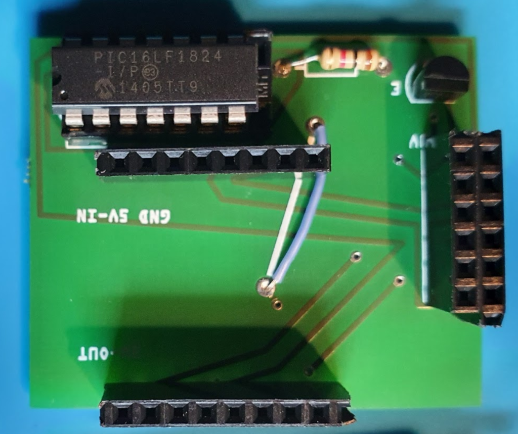
PIC 16LF1824 Low Power Microcontroller
Here comes the PIC into the game:
- PIC is sleeping
- To enable the display, its connected to a transistor that is “grounding” the display to close the power loop.
- Once this is done, it will pull-down the backlight (so it keeps disabled) and it will check the “touch IRQ” pin of the display.
- Only when detecting a touch it will pull down the RST to ground, so the ESP8266 is waking up. The nice thing of a PIC, it keeps the IO status during sleep, it doest need any other hardware to run and it can be programmed easily.
I am posting this extract, to show how easy the PIC can be used for this kind of tasks:
 while (1)
    {
        WDTCONbits.SWDTEN = 0b1;
        SLEEP(); // sleep for watchdog sleep time 1.3 sec
        WDTCONbits.SWDTEN = 0b0;

        pen_pressed=false;

        //Enable the display (without backlight) to measure if touched
        IO_RC4_TFT_BKL_OUT_SetLow();
        IO_RC3_TFT_PWR_OUT_SetHigh();

        __delay_ms(40); //time needs the TFT to boot

        PEN_value=IO_RC5_TFT_PEN_IN_GetValue()  ;

        // Pen is pressed *** Wake up display
        if (PEN_value==0) {

            pen_pressed=true;

            IO_RC0_ESP_RST_OUT_SetLow();
            __delay_ms(10);
            IO_RC0_ESP_RST_OUT_SetHigh();

            // enable TFT backlight
            __delay_ms(600); //give the ESP time to wake up
            IO_RC4_TFT_BKL_OUT_SetHigh();
        }

        // check, if the ESP allows me to sleep again
        if (pen_pressed) {
            do {
                __delay_ms(500);
                SLEEP_value=IO_RC1_ESP_SLEEP_IN_GetValue() ;
            }
            while (SLEEP_value!=0);
        }

        // Go back to sleep
        IO_RC2_TST_OUT_SetLow();
        IO_RC3_TFT_PWR_OUT_SetLow();
        IO_RC4_TFT_BKL_OUT_SetLow() ;

    }
}
ESP8266 Programming
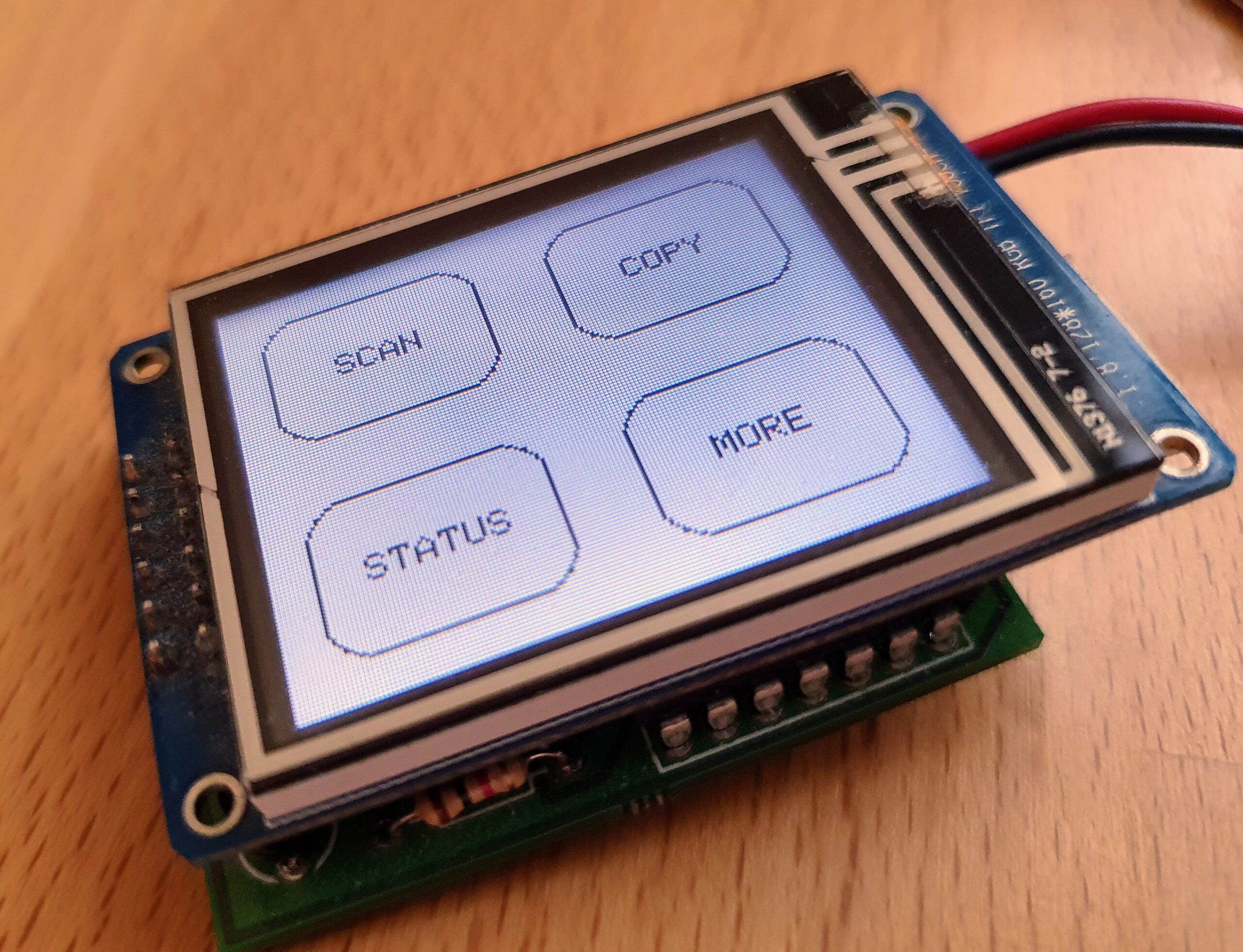
On wake up from the PIC, the ESP will take over control of the display and connect via WiFi to the SmartHome Server / DocBox Server – to register. Nothing special about this. But I wanted to be able to set-up a system to display menus and sub-menues, so I came with the following approach using AdafruitGFX-Button library and “button-press-handler” as shown below -after defining the buttons, each button is assigned to a “handler” (https://github.com/happychriss/TouchSwitch/blob/master/src/tft_helper.cpp) that will be called when the button is pressed. If each “sub-menue” is placed in its own c-file, the result is a very modular and structured.
uint main_menu() {

    //****** Paint the Display ************************************************

    DPL("**** Paint Main-Menu Display");

    tft.fillScreen(ST7735_WHITE);

    enum M1 {
        B_SCAN = 0, B_COPY = 1, B_HOME = 2, B_STATUS = 3
    };

    Adafruit_GFX_Button buttons[4];
    buttons[B_SCAN].initButtonUL(&tft, B_X_SPACE, B_Y_SPACE, B_X_WIDTH, B_Y_HEIGHT, C_BUTTON, C_BACK, C_TEXT, "SCAN", 1);
    buttons[B_COPY].initButtonUL(&tft, B_X_SPACE + (X_MAX / 2), B_Y_SPACE, B_X_WIDTH, B_Y_HEIGHT, C_BUTTON, C_BACK, C_TEXT, "COPY", 1);
    buttons[B_HOME].initButtonUL(&tft, B_X_SPACE, (Y_MAX / 2) + B_Y_SPACE, B_X_WIDTH, B_Y_HEIGHT, C_BUTTON, C_BACK, C_TEXT, "STATUS", 1);
    buttons[B_STATUS].initButtonUL(&tft, (X_MAX / 2) + B_X_SPACE, (Y_MAX / 2) + B_Y_SPACE, B_X_WIDTH, B_Y_HEIGHT, C_BUTTON, C_BACK, C_TEXT, "MORE", 1);

    for (int i = B_SCAN; i <= B_STATUS; i++) {
        buttons[i].drawButton();
        buttons[i].press(false);
    }

    global_status = GLOBAL_ACTION_MAIN_MENU;
    struct _button_handler buttonHandler[4];
    buttonHandler[0].button_action = menu_start_scanner;
    buttonHandler[1].button_action = menu_start_copy;
    buttonHandler[2].button_action = menu_start_test;
    buttonHandler[3].button_action = menu_start_more;

    return HandleButtons(buttons, 4, buttonHandler, TOUCH_SECONDS_WAIT);
}
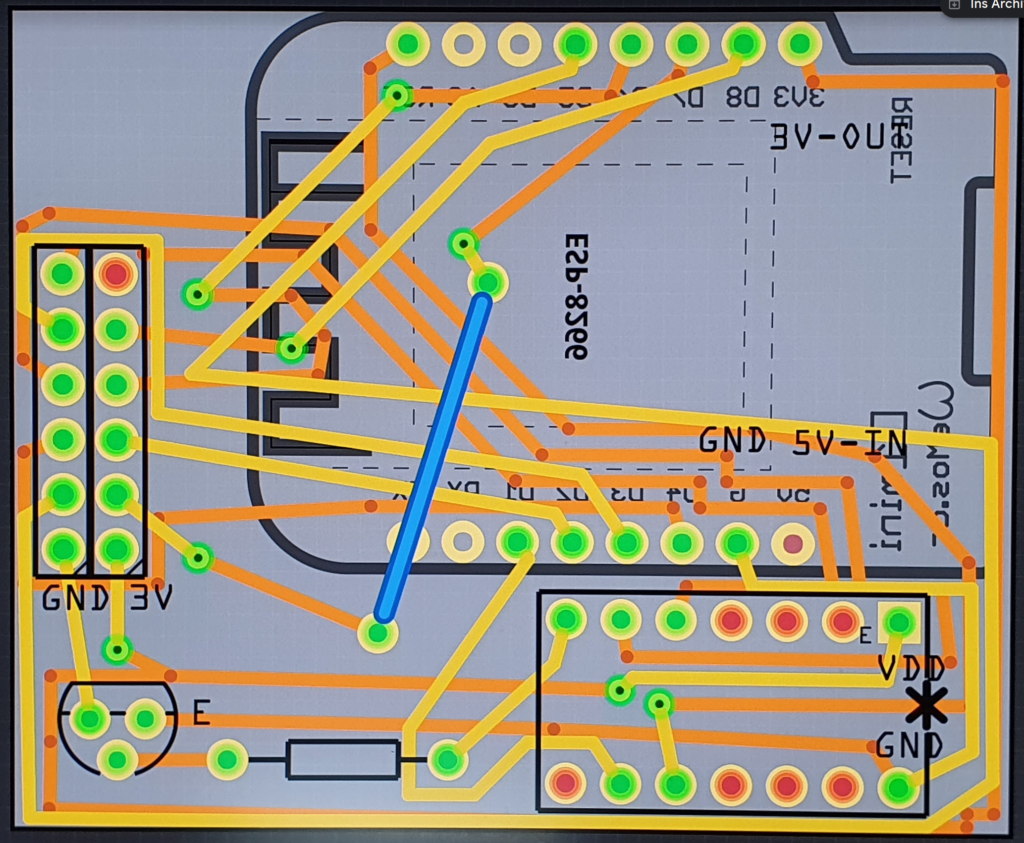
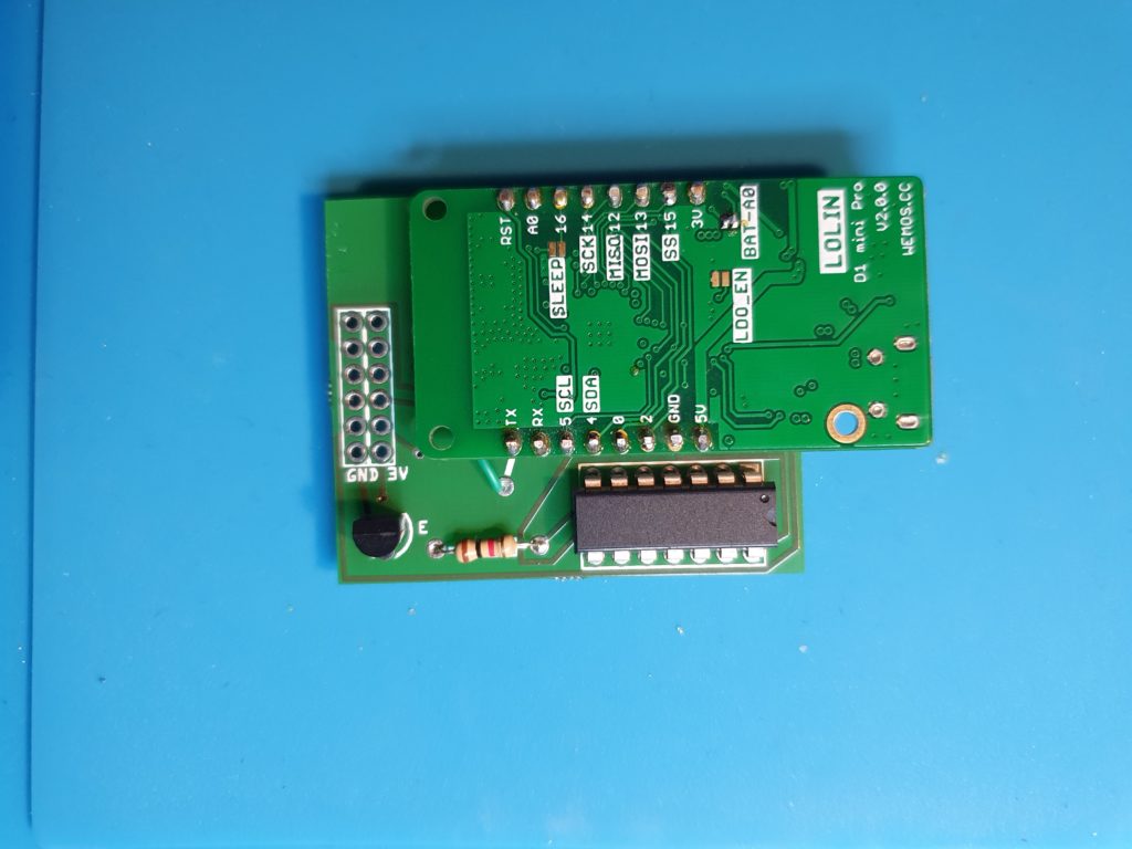
Building a PCB
Finally I realized that this will be a bit of wiring, so I did my 2nd PCB using Fritzing to layout the PCB and directly ordered it via Aisler, a German company for quick prototyping. I was very positively surprised by the cheap price and the quick delivery. Its so much easier to design the PCB then doing all the wiring.
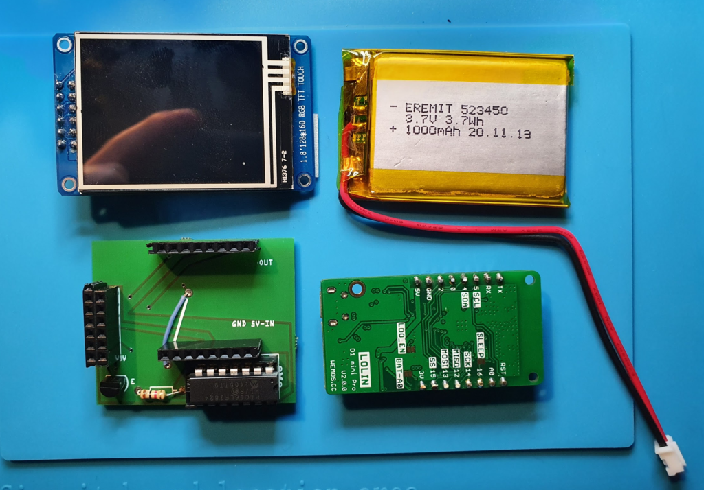
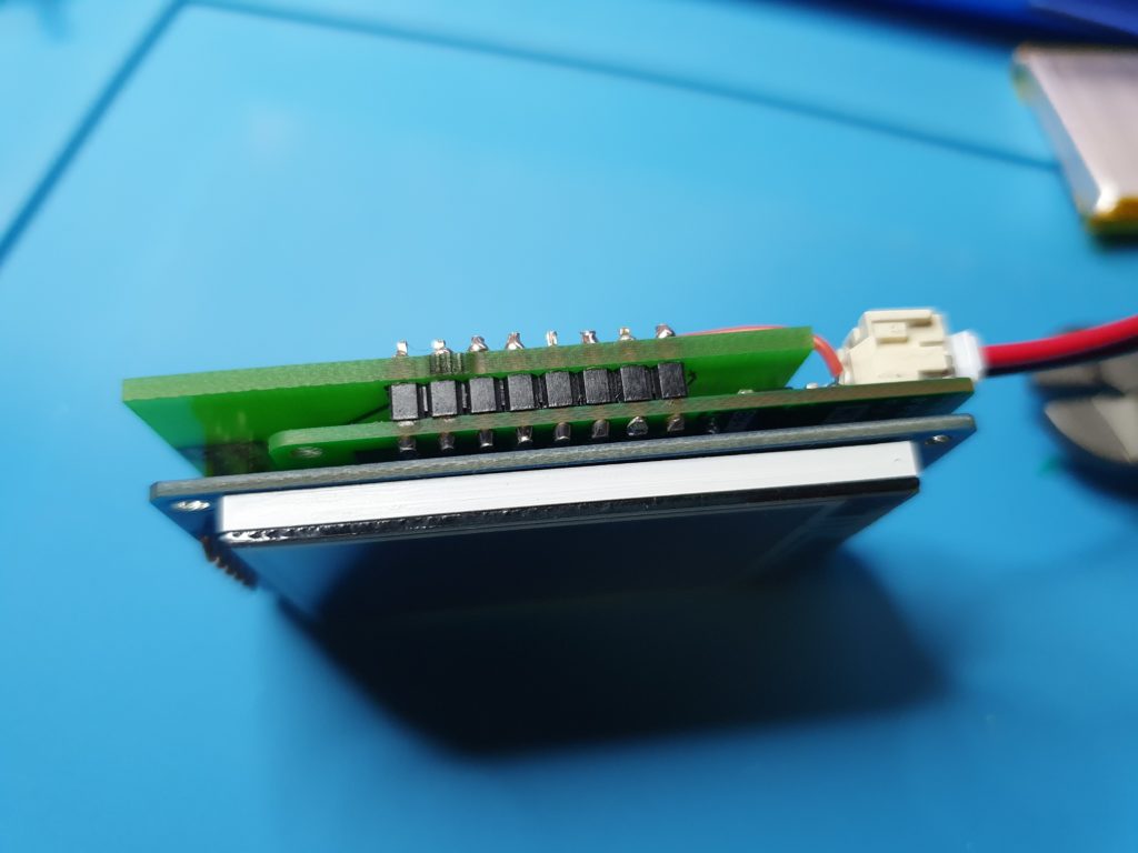
All build together – still TINY
In total the system has the following components: TFT Display, ESP8266, PIC and battery – and should still be slime. I played a lot with different layouts – that was the result. Finally (of course) the battery needs to be added. When choosing the ESP, I choosed the Wemos Mini, that comes with an integrated LiPo and LiPo charger.
What is next?
Yes …it needs a case… 🙂