44-2.de

Understanding technology by building it

Category: Self-Hosted Infrastructure and Security

  • Immich at Home: Secure Family Access Without Exposing the Server

    Immich at Home: Secure Family Access Without Exposing the Server

    Running Immich at home is always a tradeoff between security, convenience, and upload reliability. In practice, there are three common ways to expose it: direct access, VPN access, or Cloudflare in front of a reverse proxy. Each option changes both the attack surface and how well large uploads work.

    Three access models

    Direct access

    The simplest setup is plain port forwarding. It works, but it also creates the biggest public attack surface. For a private photo archive, that is usually the riskiest option.

    VPN access

    A VPN such as WireGuard is the cleanest security model. The phone connects to the home network first and then reaches Immich like an internal service. That keeps the public attack surface small because the app is not exposed like a normal public website.

    For a single user or a technical household, this is often the strongest option. The downside is usability. Every phone needs a VPN client, and it needs to be installed, configured, and active. For family members, that is often where the clean design starts to break.

    Cloudflare in front

    Cloudflare is the practical compromise. It gives the service a public entry point without exposing the Immich container directly to the internet. Immich’s own remote-access docs mention that a remote reverse proxy such as Cloudflare can improve security by hiding the server IP and making targeted attacks harder.

    That makes Cloudflare attractive when the goal is simple family access without requiring a VPN on every device. The tradeoff is that Cloudflare becomes part of the request path, and that matters for large uploads.

    Why Cloudflare was the right starting point

    For a shared family photo service, convenience matters almost as much as security. A VPN-only setup is cleaner from a security perspective, but it is harder to roll out to non-technical users. Cloudflare gives a normal app-and-URL experience without publishing the Immich service directly.

    So Cloudflare is a good first layer here. It is not more secure than a VPN-only design, but it is clearly better than direct exposure. And it solves the family access problem much better than WireGuard alone.

    The catch: large uploads

    The main downside shows up with large files. The Cloudflare path often becomes the limiting factor for uploads, and the commonly reported cap is around 100 MB on lower-tier proxied setups. That becomes visible very quickly with larger videos.

    So the real issue is not that MP4 files are special. The issue is that the Cloudflare route is convenient and safer for public access, but it is not the best path for large uploads from trusted devices.

    The practical answer

    The useful design is a hybrid model. Keep Cloudflare as the public front door for normal and family-friendly access, but let trusted devices use a direct path to the home server through WireGuard and local DNS.

    This keeps the convenience and reduced exposure of Cloudflare, while avoiding the upload bottleneck for your own phone or other trusted clients. The same Immich URL can still work everywhere. Only the network path changes.

    How the setup works

    The public path is layered so Immich is not exposed directly from Docker to the internet. Internet traffic goes to Cloudflare first, Cloudflare forwards through the named tunnel fyp, the tunnel sends requests to Nginx on localhost:8283, and Nginx proxies the main Immich hostname to the Immich container on 127.0.0.1:2283.

    In parallel, there is also a direct local HTTPS path for trusted clients. On the home network, Nginx also listens on port 443 with TLS, so LAN devices can reach the same Immich service without using the Cloudflare route.

    Sample traffic flow

    Internet
      └─► Cloudflare
            └─► cloudflared tunnel "fyp"
                  └─► localhost:8283 (nginx)
                        └─► http://127.0.0.1:2283 (Immich Docker)
    
    Local network
      └─► nginx :443 SSL
            └─► http://127.0.0.1:2283 (Immich Docker)

    Hostname layout

    A clean version of this setup can use two hostnames:

    • photos.example-family.net for the full Immich app
    • share-photos.example-family.net for public share links only

    That separation is useful because Nginx can apply different behavior by server_name even if Cloudflare sends both through the same local listener. The main app domain serves the full interface. The share domain can be restricted to share-related paths and return 403 for everything else.

    Nginx design

    The main Nginx block uses a dual-listen design. It listens on 127.0.0.1:8283 for cloudflared, and also on :443 ssl for direct local HTTPS access from LAN and VPN clients.

    The proxy config needs the headers Immich expects: Host, X-Real-IP, X-Forwarded-Proto, and X-Forwarded-For. In a Cloudflare-based setup, real_ip_header CF-Connecting-IP is important so Nginx can recover the original client IP instead of only seeing the tunnel source. X-Forwarded-Proto https and X-Forwarded-Port 443 help Immich generate correct redirect URLs behind the proxy.

    It also needs websocket support, large enough request-body limits, and timeouts that do not make the reverse proxy the first failure point during uploads.

    Cloudflare tunnel role

    The tunnel maps the public Immich hostnames to localhost:8283, and Nginx separates them by server_name. That lets one tunnel front multiple internal virtual hosts without exposing the application container directly.

    That is the real value of the Cloudflare layer here. It gives an easy public entry point for family use and reduces direct exposure of the home server. But it is still not the ideal upload path for trusted clients and large files.

    Local DNS and home access

    To avoid sending trusted home traffic through Cloudflare, the home network uses a local DNS override for the main Immich hostname. FRITZ!Box supports handing out a local DNS server to LAN clients in the Home Network → Network → Network Settings → IPv4 area, so devices on Wi-Fi can resolve the Immich hostname to the local server IP instead of the public Cloudflare path.

    That means the same URL works both publicly and privately. Outside the house it resolves through Cloudflare. Inside the house it resolves directly to the local Nginx endpoint and uses the local HTTPS path.

    WireGuard as the trusted-device path

    WireGuard extends the same idea to mobile devices. In this design, the phone connects home first, gets the private DNS behavior, and reaches the same Immich hostname through the direct path instead of through Cloudflare.

    That is the clean workaround for large uploads. Family devices can keep using the easy public route. Trusted devices such as your own phone can use WireGuard and the local DNS route for direct, more reliable uploads.

    Security assessment

    This design is more secure than exposing Immich directly to the internet. Immich stays behind Docker and Nginx, and Cloudflare reduces direct exposure of the home IP.

    At the same time, it is still not more secure than a VPN-only model. A VPN-only setup keeps the smallest public attack surface because the application itself is not exposed publicly at all.

    That is why the hybrid approach works well in practice. Cloudflare is the family-friendly front door. WireGuard and local DNS provide the better path for trusted devices, especially when large uploads matter.

    After all the Theorie – here is the detailed setup

    Step 1 — Docker / Immich

    Create /home/<user>/immich-app/.env:

    UPLOAD_LOCATION=/data/photo_archive/immich_upload
    DB_DATA_LOCATION=/home/<user>/immich-app/postgres
    
    IMMICH_VERSION=release
    
    DB_PASSWORD=<strong-random-password>
    DB_USERNAME=postgres
    DB_DATABASE_NAME=immich
    

    Create docker-compose.yml:

    name: immich
    
    services:
      immich-server:
        container_name: immich_server
        image: ghcr.io/immich-app/immich-server:${IMMICH_VERSION:-release}
        volumes:
          - ${UPLOAD_LOCATION}:/usr/src/app/upload
          - /etc/localtime:/etc/localtime:ro
        env_file:
          - .env
        ports:
          - '2283:2283'
        depends_on:
          - redis
          - database
        restart: always
    
      immich-machine-learning:
        container_name: immich_machine_learning
        image: ghcr.io/immich-app/immich-machine-learning:${IMMICH_VERSION:-release}
        volumes:
          - model-cache:/cache
        env_file:
          - .env
        restart: always
    
      redis:
        container_name: immich_redis
        image: docker.io/redis:6.2-alpine
        restart: always
    
      database:
        container_name: immich_postgres
        image: ghcr.io/immich-app/postgres:14-vectorchord0.3.0-pgvectors0.2.0
        environment:
          POSTGRES_PASSWORD: ${DB_PASSWORD}
          POSTGRES_USER: ${DB_USERNAME}
          POSTGRES_DB: ${DB_DATABASE_NAME}
          POSTGRES_INITDB_ARGS: '--data-checksums'
        volumes:
          - ${DB_DATA_LOCATION}:/var/lib/postgresql/data
        restart: always
    
    volumes:
      model-cache:
    

    Start Immich:

    docker compose up -d
    

    Immich is now reachable on the host at http://127.0.0.1:2283.


    Step 2 — Cloudflare Setup

    2a. Prerequisites

    • A domain managed in Cloudflare (nameservers pointing to Cloudflare)
    • Cloudflare Zero Trust enabled (free tier works)

    2b. Create the tunnel in the Cloudflare dashboard

    1. Go to Cloudflare Dashboard → Zero Trust → Networks → Tunnels
    2. Click Create a tunnel → choose Cloudflared
    3. Name the tunnel (e.g. my-tunnel)
    4. Follow the on-screen install instructions — this provides the cloudflared package and generates the tunnel credentials file
    5. Add Public Hostnames:
    Subdomain Domain Service
    <main-subdomain> your-domain.org http://localhost:8283
    <share-subdomain> your-domain.org http://localhost:8283

    Cloudflare automatically creates the DNS CNAME records — no manual DNS entries needed.
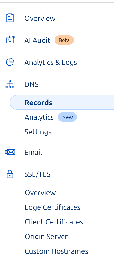
    2c. SSL/TLS setting

    In the Cloudflare dashboard for your domain, go to SSL/TLS → Overview and set the encryption mode to Full (strict).

    This means Cloudflare validates your server’s Let’s Encrypt certificate when connecting. It requires a valid cert on the server (set up in Step 3).

    2d. Install cloudflared on the server

    # Debian / Ubuntu
    curl -L --output cloudflared.deb \
      https://github.com/cloudflare/cloudflared/releases/latest/download/cloudflared-linux-amd64.deb
    sudo dpkg -i cloudflared.deb
    

    2e. Tunnel config file

    Create ~/.cloudflared/config.yml:

    tunnel: <tunnel-name>
    credentials-file: /home/<user>/.cloudflared/<tunnel-id>.json
    
    ingress:
      - hostname: <main-subdomain>.your-domain.org
        service: http://localhost:8283
      - hostname: <share-subdomain>.your-domain.org
        service: http://localhost:8283
      - service: http_status:404   # catch-all: required, rejects unknown hostnames
    
    no-autoupdate: true
    

    Both hostnames point to nginx on port 8283. Nginx routes them to different behaviours by server_name.

    2f. Run cloudflared as a systemd service

    sudo cloudflared service install
    sudo systemctl enable --now cloudflared
    
    # Verify
    sudo systemctl status cloudflared
    

    Step 3 — TLS Certificate (Let’s Encrypt)

    The certificate serves two purposes:

    • Enables HTTPS on port 443 for direct local network access
    • Satisfies Cloudflare’s Full (strict) validation when it connects to your server
    sudo apt install certbot python3-certbot-nginx
    sudo certbot certonly --nginx -d <main-subdomain>.your-domain.org
    

    The --nginx flag lets certbot temporarily use nginx to complete the ACME challenge. The cert is stored under /etc/letsencrypt/live/<domain>/.

    Auto-renewal

    Certbot installs a systemd timer that renews automatically before expiry. After renewal, nginx must be reloaded to pick up the new cert:

    # Create a deploy hook so nginx reloads after every renewal
    echo "systemctl reload nginx" | sudo tee /etc/letsencrypt/renewal-hooks/deploy/reload-nginx.sh
    sudo chmod +x /etc/letsencrypt/renewal-hooks/deploy/reload-nginx.sh
    
    # Verify the timer is active
    sudo systemctl status certbot.timer
    
    # Test renewal (dry run)
    sudo certbot renew --dry-run
    

    Step 4 — Nginx

    Nginx handles two distinct server blocks for Immich. Add them to /etc/nginx/nginx.conf inside the http {} block.

    map $http_upgrade $connection_upgrade { default upgrade; '' close; }
    
    # --- Main Immich server ---
    # Listens on 127.0.0.1:8283 (cloudflared) AND :443 (local network HTTPS)
    server {
        listen 127.0.0.1:8283;
        listen 443 ssl http2;
        server_name <main-subdomain>.your-domain.org;
    
        ssl_certificate     /etc/letsencrypt/live/<main-subdomain>.your-domain.org/fullchain.pem;
        ssl_certificate_key /etc/letsencrypt/live/<main-subdomain>.your-domain.org/privkey.pem;
    
        client_max_body_size 50000M;
        client_body_timeout 600s;
    
        # Restore real visitor IP (cloudflared connects from localhost)
        real_ip_header CF-Connecting-IP;
        set_real_ip_from 127.0.0.1;
    
        # Required for OAuth to generate correct redirect URLs
        proxy_set_header Host              $host;
        proxy_set_header X-Forwarded-Host  $host;
        proxy_set_header X-Forwarded-Proto https;
        proxy_set_header X-Forwarded-Port  443;
        proxy_set_header X-Real-IP         $remote_addr;
        proxy_set_header X-Forwarded-For   $proxy_add_x_forwarded_for;
    
        # WebSocket support (required by Immich UI)
        proxy_http_version 1.1;
        proxy_set_header Upgrade    $http_upgrade;
        proxy_set_header Connection $connection_upgrade;
        proxy_request_buffering off;
    
        proxy_read_timeout 600s;
        proxy_send_timeout 600s;
        send_timeout       600s;
    
        location / {
            proxy_pass http://127.0.0.1:2283;
        }
    }
    
    # --- Share-only domain ---
    # Serves Immich share links only; all other paths return 403
    server {
        listen 8283;
        server_name <share-subdomain>.your-domain.org;
    
        set $backend "http://127.0.0.1:2283";
    
        proxy_set_header Host              $http_host;
        proxy_set_header X-Real-IP         $remote_addr;
        proxy_set_header X-Forwarded-For   $proxy_add_x_forwarded_for;
        proxy_set_header X-Forwarded-Proto $scheme;
        proxy_http_version 1.1;
        proxy_set_header Upgrade    $http_upgrade;
        proxy_set_header Connection "upgrade";
        proxy_redirect off;
        proxy_read_timeout 600s;
        proxy_send_timeout 600s;
        send_timeout       600s;
    
        # Allow share paths and all static assets Immich needs to render them
        location ~* ^/(share|api|_app|assets/|static/|fonts/|favicon.*\.png|apple-icon-180\.png|favicon\.ico|.*\.js|.*\.css|.*\.woff2?|.*\.ttf) {
            proxy_pass $backend;
        }
    
        # Block everything else
        location / {
            return 403;
        }
    }
    

    Test and apply:

    sudo nginx -t && sudo systemctl reload nginx
    

    Key Design Notes

    • Port 8283 is the internal handoff between cloudflared and nginx — never exposed externally.
    • Port 2283 is Immich itself — only reachable from localhost via nginx.
    • real_ip_header CF-Connecting-IP is essential. Without it, Immich logs and any rate limiting see 127.0.0.1 for every request.
    • X-Forwarded-Proto: https and X-Forwarded-Port: 443 are required for Immich OAuth to build correct callback URLs.
    • The share-only domain allowlist must include /api and static file extensions — Immich loads assets from those paths even for share pages.
    • The map $http_upgrade $connection_upgrade block must be declared at the http {} level, not inside a server block.
    • The catch-all - service: http_status:404 at the end of the cloudflared ingress rules is required — cloudflared will refuse to start without it.
  • Automating LUKS Encryption Safely with Polkit and Selective sudo

    Automating LUKS Encryption Safely with Polkit and Selective sudo

    📢 Automating LUKS – Seamless Encryption &  The Battle Against sudo

    Fun fact – I used one Chat-Window with ChatGPT to find this solution, at the end I asked him to understand the objective of my questions, and used below prompt to build this post – wouhhh ( I love it how he ignores my spelling mistakes ;.))


    The Problem

    I’ve always been a fan of automation—no unnecessary manual steps, no friction, no surprises.
    When dealing with LUKS-encrypted storage and Samba shares, I had one clear goal:

    ✅ Fully automate mounting and unmounting without needing to enter manual passwords

    Actually, I have another script that gets the password via https request, so its a remote lock/unlock. The script is a simple web-server,  you will know how to do it 🙂

    That sounds simple? It wasn’t.

    The First Idea: Just Use udisksctl

    At first, udisksctl seemed perfect. A simple:

    udisksctl unlock -b /dev/sdf2

    would unlock my LUKS volume, and:

    udisksctl lock -b /dev/disk/by-uuid/XXXX

    should lock it. No root, no sudo.

    But then came the first brick wall: It asked for a password—even when running from a script.
    💬 “Wait, why does udisksctl need root to lock a device, but not to unlock it?”

    Welcome to Polkit & UDisks2—a world of undocumented edge cases.

    Polkit: The Rabbit Hole

    My next move? Polkit rules.
    It should allow passwordless execution, right?

    polkit.addRule(function(action, subject) {
        if ((action.id == "org.freedesktop.udisks2.encrypted-unlock" ||
             action.id == "org.freedesktop.udisks2.lock-device") &&
            subject.isInGroup("disk")) {
            return polkit.Result.YES;
        }
    });

    Result? Still asking for a password.
    Debugging with journalctl -f | grep polkit told me that some actions were still being denied.
    One step forward, two steps back.

    The Real Issue: fuser, Samba & Busy Devices

    Unmounting a LUKS volume is not just about stopping I/O operations—it’s about breaking any remaining connections.

    • Samba still held open files on my mounted LUKS drive.
    • udisksctl lock failed with “Device or resource busy”.
    • umount -l wasn’t enough—because smbd was still running in the background.

    I needed to force kill processes before unmounting.

    sudo smbcontrol smbd close-share LUKSShare
    sudo fuser -km /data/check
    sudo udisksctl unmount -b /dev/mapper/my_luks_drive

    💡 Lesson learned: Locking a LUKS device isn’t just about the disk—it’s about all the services using it.

    The Compromise: Selective sudo

    At this point, I had a choice:

    1. Go even deeper into Polkit and hack my way through more rules.
    2. Accept reality and selectively allow sudo—but in a controlled way.

    I chose option 2.
    Using visudo, I allowed only the required commands to run without a password:

    youruser ALL=(ALL) NOPASSWD: /usr/bin/udisksctl lock -b /dev/disk/by-uuid/*,                              /usr/bin/smbcontrol smbd close-share *,                              /usr/bin/fuser -km /data/check

    This kept security tight while making automation work smoothly.

    The Final Setup

    At the end of this journey, I had a fully working system that:

    • Mounts LUKS automatically.
    • Unmounts and locks it without requiring sudo manually.
    • Closes Samba shares properly to avoid device busy errors.
    • Uses sudo only for the absolute essentials (but without password prompts).

    Final Changes

    Below are the final changed files:

    • 📂 Mount and Unmount Scripts
      (automating the full LUKS lifecycle)
    • 📂 sudoers File
      (allowing selective passwordless sudo execution)
    • 📂 Polkit Rules
      (the necessary adjustments to make it work)

    🚀 Conclusion

    This wasn’t just about avoiding sudo. It was about understanding Linux security, process management, and automation.
    Would I do it the same way again? Probably.

    Would I recommend it to someone else?
    💡 “Only if you’re really into debugging Linux internals.”

    🚀 Final setup below. Let me know if you see ways to make it even cleaner.

    💡 This post is for those who want real, practical automation without compromising security.
    If you’ve fought the same battle, drop a comment. 🔥

    Mount

     1 #!/bin/bash
     2
     3 # Check if password is provided
     4 if [ -z "$1" ]; then
     5     echo "Usage: $0 <password>"
     6     exit 1
     7 fi
     8
     9 password="$1"
    10 device="/dev/sdx1"   # Your LUKS partition
    12 luks_name="luks-xxx"  # Custom device name
    13
    14 # Unlock LUKS partition with a fixed name
    15 udisksctl unlock --block-device "$device" --key-file <(echo -n "$password")
    16
    17 sleep 1
    18 # Mount the unlocked LUKS volume
    19 udisksctl mount -b "/dev/mapper/$luks_name"

    Unmount

    #!/bin/bash
     2
     3 # Configuration: Set your LUKS device details
     4 LUKS_UUID="luks-xxxx" 
     5 LUKS_MAPPER="/dev/mapper/luks-xxxx"
     6 MOUNT_PATH="//mount_point"  # Mount point
     7 SAMBA_SHARE_NAME="smb_share"  # Samba share name
     8 DEVICE="/dev/sdx1"
     9
    10 # Close active Samba connections
    11 echo "Closing Samba share: $SAMBA_SHARE_NAME..."
    12 sudo smbcontrol smbd close-share "$SAMBA_SHARE_NAME"
    13
    14 sleep 1
    15
    16
    17 # Unmount the LUKS volume
    18 echo "Unmounting LUKS volume..."
    19 sudo udisksctl unmount -b "$LUKS_MAPPER" || umount -l "$LUKS_MAPPER"
    20
    21
    22 # Kill all processes using the mount point
    23 #echo "Killing active processes on $MOUNT_PATH..."
    24 #sudo fuser -km "$MOUNT_PATH"
    25
    26 # Wait for system to release resources
    27 sleep 1
    28
    29 # Lock the LUKS device
    30 echo "Locking LUKS device..."
    31 sudo udisksctl lock -b "$DEVICE"
    32
    33 if [ $? -eq 0 ]; then
    34     echo "LUKS device successfully locked!"
    35     exit 0
    36 else
    37     echo "Failed to lock LUKS device."
    38     exit 1
    39 fi
    40
    41 sleep 1
    42
    43 echo "Set HD to sleep mode"
    44 # sudo hdparm -y "$DEVICE

    Sudo File:

    docbox ALL=(ALL) NOPASSWD: /usr/bin/udisksctl lock -b /dev/sdf2 , \
                                /usr/bin/udisksctl unmount -b /dev/mapper/*, \
                                /usr/bin/smbcontrol smbd close-share *, \
                                /usr/bin/fuser -km *, \
                                /usr/sbin/hdparm -y /dev/sdx1
    

    Polkit Files:

    polkit.addRule(function(action, subject) {
        if ((action.id == "org.freedesktop.udisks2.encrypted-unlock" ||
             action.id == "org.freedesktop.udisks2.filesystem-mount" ||
             action.id == "org.freedesktop.udisks2.filesystem-unmount-others" ||
             action.id == "org.freedesktop.udisks2.unmount" ||
             action.id == "org.freedesktop.udisks2.lock-device" ||
             action.id == "org.freedesktop.udisks2.encrypted-unlock-other-seat") &&
            subject.isInGroup("disk")) {
            return polkit.Result.YES;
        }
    });


  • Driverless Network Printing on Ubuntu with CUPS and IPP

    Driverless Network Printing on Ubuntu with CUPS and IPP

    Just some stuff I learned after a long Sunday on printing:

    Setup:

    • HP107w printer connected via USB to a local server
    • CUPS installed on this server

    Requirements:

    • print from local server, e.g. via echo "This is a test print" | lp
    • print from any desktop PC (windows or Linux from my network)
    • driverless installation -no need to install the HP 107 driver
    • Do not use the Wifi-Part of the printer – dont like to have it enabled

    Solution:

    • Driverless printing: use IPP:Everywhere – that is a protocol where the printer gets pdf or postscript and manages the rest by itself – no need to install a driver
    • Use ipp-usb on the local server to connect the USB printer and make it available via ipp, once installed it looks for usb-printers, that should be visible via lsusb before
    • Find the ipp-url of this printer, this is the URL to reach the printer *locally* , magic command is below, check that (USB) is there
      • sudo lpinfo -v
        network ipp://HP%20Laser%20107w%20(HPF4390959C9CB)%20(USB)._ipp._tcp.local/
    • To make the printer available in the network, you have cups installed on the local server,  the trick to configure cups:
      • create new printer, and select “Internet Printing Protocoll (ipp)
      • image.png
      • on the next page copy the ipp-URL just connected.
    • CUPS moves the printer from the local domain and makes it available on the network.

    Result:

    • Printing from Linux works fine
    • Printing from Windows is still a bit buggy .. following up on this


  • Securing a Home Server with Cloudflare Tunnel

    Securing a Home Server with Cloudflare Tunnel

    A few hours back, I had a straightforward problem: I needed to access my local server securely from the internet without opening it up to unwanted access.

    What triggered this need was my own app Free Your Photos  – that gets you out of the Google Photo Cloud and hosts your photos on a local server – YOU OWN THEM. Now with this solution I can show my photos on any PC – even without a VPN.

    My first instinct was to use a VPN – but this would require a VPN installed on the “browser side”, so I would not be able to access my page from any other computer or phone.

    But – what about accessing my local-server from EVERYWHERE without any VPN setup – but still having security?

    That’s when I stumbled on the idea of using a reverse proxy with multi-factor authentication (MFA). Instead of opening the whole network like a VPN, a reverse proxy could act as a gatekeeper, allowing access only to the server itself and only to authorized users. I set it up to require Google Authenticator, so even if someone got to the login screen, they’d need a time-based code to get through.

    ChatGPT gives a pretty good instructions for all the steps that worked right away for HTTP. But to get HTTPS working I needed some  fine-tuning:

    My configuration: Using Pything with Gunicorn and nginx on Ubuntu.

    What I needed to do special:

    Domain Registration

    • Register a domain on Cloudflare
    • Assure came record is your domain-name and pointing as target to your tunnel, e.g. “345234-1420-4c4e-b8e4-86f8a885ba7a.cfargotunnel.com”
    • Download Origin – Certificates: SSL/TLS->Origin Server – that are used to authenticate the local server against Cloudflare, save them in a folder accessible by nginx web server.

    Tunnel Configuration

    ZeroTrust – Config => Network => Tunnels => Cloudflared

    Type: https, URL: localhost:443
    TSL: NO TLS Verify

    Nginx Config

           listen 443 ssl http2;
           listen [::]:443 ssl http2;
           server_name <your domain name>;
    
            ssl_certificate /etc/ssl/certs/cloudflare_cert.pem;      # Path to your SSL certificate
            ssl_certificate_key /etc/ssl/certs/cloudflare_key.pem;  # Path to your private key
    
            location / {
                include proxy_params;
                proxy_pass http://unix:/home/cneuhaus/FreeYourPhotos/fyp.sock;
            }
        }
    

    Google Authentification

    Access should only be for myself, so I wanted to use Google as authentication provider. For simple steps ChatGPT again is your friend.

    But I only wanted access for myself – otherwise everybody with google account can login, for this:

    Zero Trust=>Settings=>Authentification=>Login Methods, enter App-ID and Client Secret.
    
    Zero Trust=>Application (create new one) =>Policies=>Configure Rules=> add your full Gmail address here
  • Building a Quiet Ubuntu Home Server with a ZOTAC ZBOX

    Building a Quiet Ubuntu Home Server with a ZOTAC ZBOX

    Intro

    This will be my new “HomeServer” running https://44-2.de/docbox/ and Openhabian..and more. Its a passive cooled mini PC with Intel i3-8130U, for my needs its equipped with 8GB RAM and a 8GB (2x4GB) Crucial DDR4-2400 CL17 SO-DI RAM and a Samsung SSD 860 EVO Series 1TB.

    Installing the Hardware


    https://www.youtube.com/watch?v=SizIpEPl378

    Installing Ubuntu 20.04 LTS on ZOTAC ZBOX + The Bacis

    Very simple and straight forward

    • Create Bootable USB Stick with Etcher
    • Connect with Keyboard , HDMI Monitor and Ethernet (optional)
    • PlugIn USB Stick in the front USB
    • Power on the box + press F8 on the keyboard (every 1-2 seconds)
    • Boot Menu: Enable UEFI – Boot (if you like) + Reboot
    • Again press F8 and select USB as boot-device
    • Follow the standard Ubuntu Setup (goes really fast), reboot
    • Install WIFI: Install wpa tools: sudo apt-get install wpasupplicant
    • Follow https://linuxconfig.org/ubuntu-20-04-connect-to-wifi-from-command-line to set-up the interface using netplan, my config file for WiFi located in //etc/netplan see below. To use the local name service (e.g. by your router, e.g. AVM Fritzbox) you need to add the section “search”.
    • I got error messages in dmesg about Active Power State management, to fix follow https://www.thomas-krenn.com/de/wiki/PCIe_Bus_Error_Status_00001100_beheben. This will deativate a power-status in the PCI, from short research I think its not to bad for power consumption
    • Some other error messages came from multipath tool, used on server to manage LVM devices – not needed, we only have one SSD, so I removed it with
      sudo apt-get remove multipath-tools
    # //etc/netplan config code for wifi interface (check the name of the interface, here its wlp3s0)
    network:
       ethernets:
         enp1s0:
           dhcp4: true
       version: 2
       wifis:
           wlp3s0:
             optional: true
             access-points:
               "YOUR SSID":
                   password: "YOUR PWD"
             dhcp4: no
             addresses: [YOUR IP/24]
             gateway4: 192.168.1.1
             nameservers:
               search: [fritz.box]
               addresses: [192.168.1.1]

    Install openHAB Smart Home on Ubuntu 20.04 Server

    There are two ways to install Openhab, one as a normal package or the other one as from the “openhabian” project. That starts with a config-tool, from here you will install Openhab. I can really recommend using this options. Instructions can be found here:https://www.openhab.org/docs/installation/openhabian.html#other-linux-systems-add-openhabian-just-like-any-other-software.

    Small Tips

    OpenHABian configuration tool also allows to add additional components, I went with “Log Viewer” and “MQTT Mosquitto”.

    I had to migrate from an existing openHAB installation, and used this trick: https://community.openhab.org/t/how-to-transfer-configuration-from-one-openhab-to-another/92784 that basically create a backup and restore via


    #on source: sudo openhab-cli backup --full


  • BigPi: Building a Raspberry Pi 4 Home Server with SSD Storage

    BigPi: Building a Raspberry Pi 4 Home Server with SSD Storage

    What I want to do!

    I am using a mini PC “Cubietruck / Cubieboard 3″ as server for DocBox and a Raspberry Pi 3 for home-automation with Openhabian. Now I have the LoRa-Node (Server) on an ESP8266. I want to run it all on one system and have some peace for the next years. I think Raspberry is a good platform with long maintenance and good support.


    Setting up the RPI-4

    Components:

    1. RPI4 with 4 GB Ram (the best version)
    2. Samsung SSD T5 500 GB
    3. dezen USB Charger

    Installation

    Prepare SD Card

    I want to directly install Raspbian and on initial boot access it via SSH (no HDMI needed). For this SSH and WLAN have to be configured on the boot SD card.

    Download latest Raspbian Buster Lite

    Copy it to SD Card (e.g. for linux using Etcher) and manipulate the SD card folder and files on your linux PC before inserting into the RPI as follow:

    1) Enable SSH: Place a file named ‘ssh’, without any extension, onto the boot partition of the SD card
    2) Enable remote-login with su, edit: //etc/ssh/sshd_config and set PermitRootLogin yes
    3) Update WIFI Configuration /etc/wpa_supplicant with following:

    <br />
    ctrl_interface=DIR=/var/run/wpa_supplicant GROUP=netdev<br />
    update_config=1<br />
    country=DE<br />
    network={<br />
    ssid="your-ssid"<br />
    psk="you-pwd"<br />
    }<br />

    Boot from USB

    New RPI can not yet boot directly from USB, but can be “tricked” by give him the SD card for boot, and set the SSD as root folder. A really good description can be found here:

    https://www.tomshardware.co.uk/boot-raspberry-pi-from-usb,news-61081.html

    Security and Login via SSH

    Connection to the Pi goes via SSH, to avoid typing in the PWD each time – we use SSH keys. For testing purpose the PI runs on SSH-Keyfile without passphrase question (less secure, but its only for a test-system). I also have another SSH-Keyfile (for other purposes) with a passphrase, so I need to create a new SSH-Keyfile only for the PI.

    Concept: The PI will contain a file “authorized_keys” that has a list of *trusted* clients that can connect via SSH. The client will generate a key-pair and copy his public-key to the PI “authorized_key”. On authentication the client will use his private-key to prove that he own the public-key.

    On PI – first create a new user:

    <br />
    sudo adduser username<br />
    sudo usermod -aG sudo username<br />

    Log-Off and Log-In with new user via SSH and PWD – to prepare the ssh folder. It will contain a file with public keys of authenticated servers that can login into the PI.
    <br />
    cd ~<br />
    mkdir .ssh<br />
    chmod 700 ~/.ssh<br />

    On your PC (descriptions are for Linux/Ubuntu) edit the file ~./ssh/config. Each line is one key-file use (Tip from Stackoverflow)
    <br />
    IdentityFile ~/.ssh/id_rsa<br />
    IdentityFile ~/.ssh/id_rsa_pi<br />

    Generate a new key-file via ssh-keygen, make sure to use the file-name from above and copy the file to the authorized_keys of the PI with
    <br />
    ssh-copy-id -i ~/.ssh/id_rsa_pi new_user@pi<br />

    Login into the PI from the PC should now be possible just with ssh user_name@pi.

    Latest News
    • Thank you for your order with Banggood – or how to build a Smart Home Switch for $4.00 (26.01.2020)

      It all started with an article in my favourite computer magazine Heise – WLAN Plug with Tasmota. So I could control some 220V devices, like a floor lamp with my OpenHAB Super-Cheap – Smart Home Solution Smart Home.

      Some 220V devices don’t need a plug, I want to control them with a tiny switch and not a big plug on the wall, here I found this- 4€ each from China…will this work?

      After one month of waiting, 3 arrived. Looked actually quite good!

      Its actually amazing, what you get for 4€, and ESP8266 micro computer with WiFi and all the hardware to control 220V / 10 A = 2200W)

      But: Its firmware is from China, you need to register an account somewhere and the little switch will connect to it and send your data somewhere – I cannot control.

      Wo we need to exchange the firmware on the switch, the brand “Sonoff” is well known for an “easy to way” to do this

      The firmware solution of my choice is Tasmota, an OpenSource SW that connects the device only into the internal WiFi network and provide a user-interface to configure the device. So we need to do 2 things to get it running:

      1. Flash new Firmware flashed on the switch
      2. Integrate the switch into OpenHAB (smart home open source SW)

      Preparation

      Pretty easy thing (all here: Details), you need:

      1. Image “tasmota.bin” from Tasmota: https://github.com/arendst/Tasmota/releases
      2. Flashsoftware to reprogram the device with the image from 1): tasmotizer
      3. A wire to to connect your PC via an FTDI (serial2USB converter) with the switch, the FTDI and the switch have signs on it, so has the switch:
        Edit
        FTDI Sonoff Smart Swtich
        3V 3V
        GND GND
        TXT REC/RXI
        REC/RXI TXT

        It takes 5min of soldering, when ready it should look similar to below:

      Flashing

      The switch needs to be connected with the PC via our nice cable, it just works by putting it in and a bit of adjusting.

      To get the switch in the “programming mode” the reset-button on the switch must be pressed *before* connecting the switch via USB cable to the PC. Once connected, you can release the reset-button (its the long black stick).

      Then start flashing with tasmotizer by selecting the firmware and the USB interface:

      After re-power the switch, it opens an access-point and you can be configured via connecting to its WiFi (some AP with “tasmota” in the name) , so it will later connect to your own WiFi. But much more elegant, you can use tasmotizer via the button “send config” to update the WiFi directly, you will need to enter the credentials (SSID and PWD from your home network).

      All your credentials and data remain will remain in your network now. On the router I also disabled the internect-connection for the IP address of the switch in my home network – just to be save 🙂

      Configure the Switch – Tasmota is great

      When all works, the switch will connect to your home WiFi, you can find its IP address in your Router and you can open its main config page via a web-browser. You will see the new firmware from “Tasmota” active, that gives you full control over the device.

      Its an amazing software, full Opensource, not cloud connection or internet needed. It stays in you home 🙂

      The basic tasmota configuration is already correct, nothing to do, maybe in the settings section, you may enter a backup WiFi address – if you want.

      Connecting to OpenHAB

      The Switch Side

      The concept is, that the switch will use the MQTT protocol to communicate with OpenHab, once configured the switch will listen for a message via this protocol and do its job – ON/OFF.

      To configure MQTT you need configure your OpenHab server IP and the credentials of the MQTT network, that you have configured in OpenHab. The trick is the “topic”, that is the “address” that the switch will listen towards – any message with this topic will be processed by the switch. For my network I gave each switch its own topic, like “sonoff1”, “sonoff2” – so I can control them separately. OpenHab has a binding that keeps the link to this protocol and its easy to configure.

      The OpenHab Side

      After installing the MQTT Binding in OpenHab, I did the following configuration, important to have the topic “sonoff1” correctly everywhere:

      Bridge mqtt:broker:OH2mqtt "MQTT Broker" @ "MQTT" [
          host="192.168.1.106",
          port=1883,
          username="OpenHAB",
          password="xyz"
      
      ] {
          Thing topic sonoff1 "Sonoff1" @ "MQTT" {
           Channels:
           Type switch : ch1  "Light1" [ stateTopic="sonoff:stat/sonoff1/POWER", commandTopic="cmnd/sonoff1/POWER" ]
          }
      }

      To enable and disable the switch, its straight forward:

      Switch Sonoff1 "Light1"  	 	 	 	 	 	 	 	<light> ["Switchable"] { channel="mqtt:topic:OH2mqtt:sonoff1:ch1" }
      
       sendCommand(Sonoff1,ON)</light>

      Enjoy 🙂

    • About Amazon Dash-Buttons, and what you can learn from it about IoT and Amazon! (19.01.2020)

      I am using Amazon-Dash buttons in my home automation project, got them from eBay for some euro. So I can switch-off all lights and heating from my bed, dim the lights in the living-room when watching TVs. And all for nearly no money. The buttons a made for 1000 clicks, so I thought I would be save.

      But I didnt realize the “power of Amazon” and under-estimated the SW and HW that is build into this little button.

      My plan – how to use the “Dash-Button” in Home Automation!

      Amazon did everything to make the button not useable – except for ordering from Amazon 🙂

      But smart people found a solution: You set-up the button once with the Amazon App (to let him connect to your WiFi network by providing SSID and PWD) .

      When the button is pressed, it wakes up and needs to re-connect to the configured WiFi , this connection event can be monitored with a simple script to install on  RPI HomeServer with Openhabian: https://github.com/Nekmo/amazon-dash

      sudo apt-get remove python3-pip; sudo apt-get install python3-pip
      sudo pip3 install amazon-dash
      <code class="yml">sudo systemctl start amazon-dash 

      Finally you need to configure the buttons (name, mac-address)  to be controlled in a config-file That’s it – you can access the button from OpenHABian like any Hue device.

      Ohnn…not really…..its important you make it impossible for the button to “CALL HOME” to Amazon (e.g. with a FritzBox you disable internet for fixed IP address of the button).

      The big disappointment!

      One day, one button stopped working.It seems that the battery is empty. Ok, no problem – took me a while to open the case  – and I replaced the battery.

      Nope..not working...of course the button forgot anything about WiFi and PWD. So I wanted to use the Amazon-App to save this settings.

      Nope..not working..Amazon has changed the App, no menue-item any-more for Dash-Buttons. So, how to teach the button about the WiFi?

      While doing research I learned more about this button, and had an interesting evening, starting here: https://github.com/danimtb/dasshio/issues/93

      My “Dash-Button” is a little WebServer with Access Point!

      During Reset the button opens it own WiFi AP, so you can access him via: http://192.168.0.1 from a browser of the device in this local WiFi. It tells you e.g. the firmware version. The button also allows to set-up the WiFi SSID and PWD with http://192.168.0.1/?amzn_ssid=SSID&amzn_pw=PASSWORD.

      My “Dash-Button” can update its firmware and validates certificates!

      Nope..not working.. this tiny buttons has a firmware, and when connected to the internet, it automatically updates the firmware (could you imagine, this little thing..). As of a recent version of firmware, that button wants to connect to an Amazon Server and is validating its certificate before he is saving the WiFi information. Amazon has disabled the server, because of the certificate validation you can not “fake” an Amazon server. No way to convince the button to save the SSID and PWD 🙁

      So…is there a way to get an older version of firmware or maybe a firmware hack?

      My “Dash-Button” has a microphone !

      In case WiFi is not working, the Dash-Button can be configured using *sound*, so it has a little microphone and it will load its setting from the mobile via audio. Some really smart people found a memory leak in this interfaces and managed to use this leak to implement a new version of the firmware that would skip the certificate validation. I found this on github: https://github.com/znuh/dashbutton

      So, you download the wave-file, reset-the button, play the wave-file and afterwards http://192.168.0.1/?amzn_ssid=SSID&amzn_pw=PASSWORD will work again, because the button will not ask for the certificate.

      Trying it, it first looked great – the button reacted on the sound, but:

      Nope..not working.. I found out, that my button had a recent version of the firmware and that Amazon has fixed this bug in the new version.

      My “Dash-Button” gets a *Packet of Death* from Amazon!

      I also learned that (at the moment) any Dash-Button now would connect to the internet, it will receive a special command to completely disable itself by going into an endless-loop.

      Conclusion – The POWER OF AMAZON

      I spent a full evening with my Dash-Button, a bit disappointing that I couldn’t get it back to live, but a very interesting learning experience.

      How much effort and brain-power Amazon put into this button with a functionality that is completely invisible to the user – who only things he buys a button. And that has even a microphone. And also how much power does Amazon have, the company just decided that the buttons should not be used any-more, updates the firmware, sends a packet of death and disables the certificate server. Now you have just a  peace of dead electronic to through away.


      Makes me thinking….how much sensors and computing power is in a mobile phone or an robotic vacuum cleaners. And how much power do we have about this devices – if we even cant control a simple button 🙂


    • Touchdisplay running on ESP8266 (Wemos) – RPI Remote Controll (22.09.2019)

      Introduction

      I am using a 1.8 Inch LCD Screen SPI Serial Port Module TFT Color Display Touch Screen ST7735 (128*160)  for Arduino”, bought for 9€ from aliexpress.com.

      Details: Display Processor: ST7735, Touch Processor: XPT2046, Display Type: ZJY180-TV2.0,128*160, as ESP8266 I am using the WEMOS D1 Mini Pro (v 2.0) https://wiki.wemos.cc/products:d1:d1_mini_pro.

      Its part of my Project “BigPi” to use the PI4 as my central home server. I decided it needs a display.

      Things should look nice..so what did I do?

      Actually I got the Touchdisplay running at the RPI after a lot of tries  – but what do I have on my desk:  A big black RPI4 box with a touch-display. Not looking good.

      My alternative: I build a tiny Touchdisplay with ESP8266 in a little box with battery, that I can place anywhere. I will communicate via WIFI to my RPI. No black box on the desk, just a cool multifunctional switch and status-display for RPI Remote control. Kind of a long running project – lets see how it goes.

      Wiring – how to get it together

      Of course, from china – there is not much documentation. Below some information I found at AliExpress about the display and all contacts at the display have labels. To note: PEN (11) is high, and gets low, when the display is touched – so can be directly linked to the Wemos (see below).

      Information from Vendor
      Mapping TFT Panel to Wemos

      Some Details about the WEMOS D1 Mini Pro

      Understanding the Solder-Pads

      This is a very nice ESP8266 processor, small size and including LiPo charger unit, so any 3.7V battery can be directly attached on it and can be charged via the mini USB. Its Pin-Compatible to the well known WEMOS Mini, that has some interesting soldering-pads on the back:

      • SLEEP: This connect the Reset and the XPD_DCD – Deep Sleep Wakeup, so the WEMOS can waket-up itself from Deep-Sleep. For easy programming and the serial interface to work, this should not be connected. So do it, before you put it into production
      • BAT-A0: Links the battery power to the analogue A0 input, so its possible to measure battery voltage (to detect low battery).
      • LDO_EN: To disable the 5V regulator, so you can provide your own power source directly to the 3v3 and GND pins. Useful for battery operations. If you use standard lithium ion batteries that have 3.7-4.2V, it’s better to connect them to the 5V pin, since that is connected to an LDO converter.
      back side of the board
      Deep Sleep…tzzzzz…

      I need “Deep Sleep” with ultra low power consumption, as it should run for a long time.

      I measure current 0,15mA (150uA) out of the box for the WEMOS Pro Mini via the ESP.deepSleep(), with a 1200mAh LiPo it comes to 300 days.

      If its running with display connected, but without backlight (BLK to GND), its consuming 0.48 mA (500uA) – what is approx 100 days runtime, 3 month is ok 🙂

      When the display is active and backlight is on, it consumes around 20mA, when the display is off -it goes down to 1mA.

      To Remember

      During the Deep Sleep period GPIO_16 are held high. At the end of the Deep Sleep period GPIO_16 goes low, pulling down the Rest Pin (Reset Pin is low active, eventually add 1-10k resistor in between) and restarting the Wemos.

      Prolem is, that when ESP8266 goes into DeepSleep, all IO are goint go High – so my display is “on”. It will need an inverter.

      SPI – Confusion

      SPI did confuse me, it has 3 lines MISO, MOSI and clock, the same I found on the touch-display. At the end I realized that it has 2 controllers, one for the touch sensor, and the other one for the display. Both are connected at the the same SPI bus and are selected based on chip select. So it somehow looks like below:

      SPI Logic on the TFT/Touch Display

      Software – How to get it running?

      I am using CLION from JetBrains and Platformio for development -what I can really recommend to do. The following libraries support both controllers:

      Adafruit ST7735 and ST7789 Library
      Adafruit GFX Library
      XPT2046_Touchscreen

      Thanks to this great libraries, below makes you paint on the little display with a pen, just some lines of code.

      void setup(void) {
      tft.initR(INITR_GREENTAB); // initialize a ST7735S chip, CN: My-chip has a "green flag at the protection foil"
      tft.setRotation(1);
      tft.fillScreen(ST7735_BLACK);
      ts.begin();
      ts.setRotation(0);
      
      delay(500);
      
      tft.fillScreen(ST7735_BLACK);
      testdrawtext("Welcome", ST7735_WHITE);
      delay(1000);
      tft.drawPixel(150, 118, ST7735_GREEN);
      
      }
      
      void loop() {
      
      if (ts.touched()) {
      TS_Point p = ts.getPoint();
      tft.drawPixel(p.y * x_tft_scale, p.x*y_tft_scale, ST7735_GREEN);
      }
      delay(5);
      }

      Mission completed 🙂

    • Migrating from MySQL to Postgres (25.07.2019)

      I am having some trouble on the RPI 4 to get Rails installed and finding the right version of MYSQL (MariaDB) and ActiveRecord while running an older version of Rails and a newer version of Sphinx (search index). Anyway I always wanted to move to PostgreSQL…thats the time to do.

      The tool of my choise: PGLoader

      I realized pgloader does not like to run on the RPI, but the solution is easy:

      SourceDB (Cubietrack) <-> Linux PC (my desktop) = Running PG-Loader <-> TargetDB (RPI4)

      I wanted to have the schema on the target-db, as original as possible for Rails, so I used rake:
      <br />
      rake db:create<br />
      rake db:schema:load<br />

      to have an original Rails DB set-up. PGLoader is used for data-migration.

      Script:
      <br />
      LOAD DATABASE<br />
      FROM mysql://export:xxx@ct/CTCD2Server_production<br />
      INTO pgsql://docbox:xxx@pi:5432/docbox_production<br />
      with data only<br />
      ALTER SCHEMA 'CTCD2Server_production' RENAME TO 'public';<br />

      Two important points:

      1. The last statement “alter schema” is important, as pgloader creates a schema with the same name as the source db and creates all table in this schema – and rails may not expect this.
      2. “with data only” – tells pgloader that the schema is already existing (rake db:schema:load)

      Once, I got the script working – data migration is just a “button press”.